Introduction
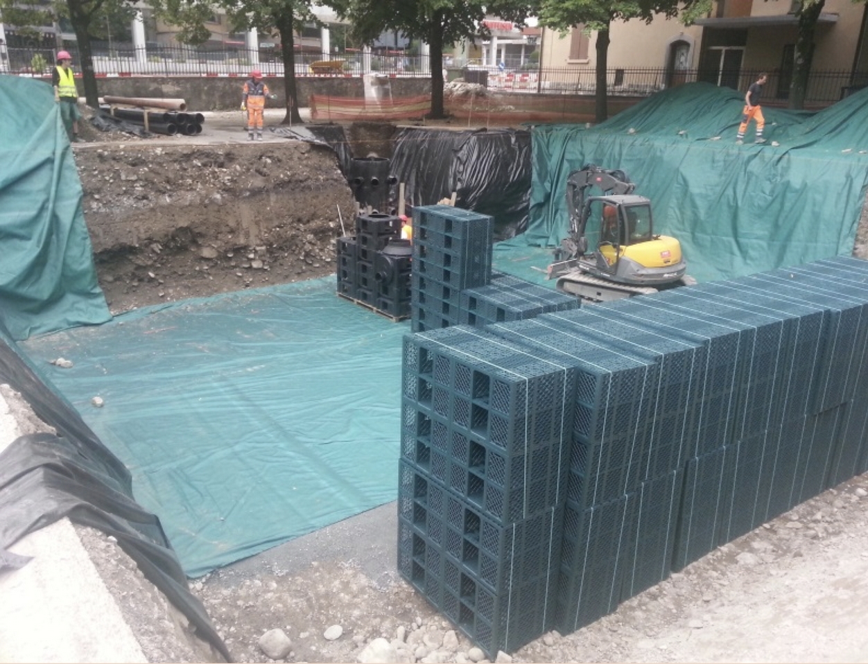
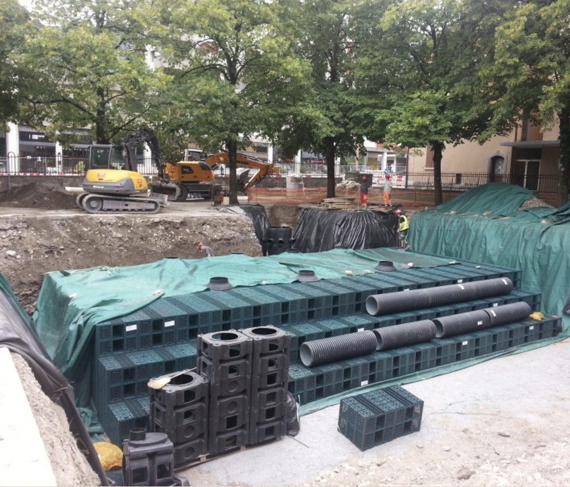
The Rigofill Inspect® modular block makes it possible to meet the various planning and construction constraints. Compared with gravel drainage trenches and traditional concrete basins, this technological solution offers an interesting technical, economic and environmental alternative. With Rigofill® modules, the costs of installation, excavation, removal of earthworks, labour, maintenance or masonry equipment are reduced to a minimum.
Rigofill Inspect® modules substantially increase the storage volume of an infiltration or retention facility. The configuration of the modules makes it possible to obtain a very high water storage volume and to save space compared to gravel drainage trenches of a comparable volume. In addition, depending on the available surfaces, the pipe levels and the burial depth, many configurations are possible thanks to Rigofill Inspect® modular elements.
This product, which has been on the market since 2001, is the only product to have obtained the following three approvals : CSTB (French approval), BBA (UK approval), and DIBT (German approval).
Additional information
The two types of Rigofill Inspect® modules, i.e. the whole module and the half-module, make it possible to adapt the dimensions of the retention or infiltration basins according to the size of the site. These modules have the following advantages :
- 95% working volume: Rigofill Inspect® has a storage volume of 95% and therefore a storage volume 3 to 4 times greater than gravel.
- Installation: The installation of Rigofill® modules is quick and easy thanks to the fitted elements, the reduced number of various elements and its lightness. The connection between the elements is guaranteed by assembly clips which are very easy to set up.
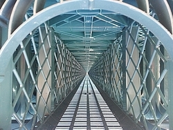
- Video inspection: Rigofill Inspect® makes it possible to inspect the installation at any time and, if necessary, to clean it.
- Longer service life: The service life is guaranteed for at least 50 years (under appropriate condition of use). In the case of infiltration, cleaning is necessary to maintain sufficient permeability of the geotextile over time.
- Versatile use: Modules can be used for infiltration, retention and storage of water.
- Reliability: The presence of these modules on the market since 2001 demonstrates their reliability. The mechanical strength is proven by these three certifications : CSTB / DIBT / BBA.
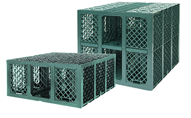
Complete module
- Size : L 80 cm x l 80 cm x H 66 cm
- Storage capacity : 400 liters
- Weight : 20 kg
Half-module
- Size : L 80 cm x l 80 cm x H 35 cm
- Storage capacity : 211 liters
- Weight : 12 kg
The Rigofill Inspect® half-module is ideally used in installations where the height is limited, for example when the groundwater level is high or when the traffic loads are close to the upper level of the modules. The advantages mentioned above are also valid.
End plates
The perforated end plates allow a direct connection to the network of up to Ø 200 mm. For larger diameters, a Quadro-control® chamber should be used. They are also used to close the ends of the basin.
 |
Front adapter |
 |
Panel adapter DN 150 KG |
 |
Panel adapter DN 200 KG |
ASSEMBLY CLIPS
Thanks to its single or double chamber fittings, the Rigofill® structure can be installed quickly and maintains a perfect connection between the modules.
 |
Half-chamber on one level |
 |
Half-chamber on several levels |
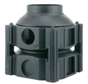
QUADRO-CONTROL® CHAMBER
Quadro-control® chamber can be integrated without problem into any single, two or three-level basin, thanks to its dimensions compatible with the Rigofill Inspect® module and its modular construction. This chamber has the same dimensions as Rigofill Inspect® modules. It allows access to the retention basin for inspection and cleaning work and a direct network connection for diameters up to 600 mm.
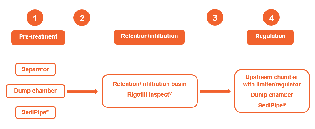
The operating principle of a retention basin is as follows :
- Recovery of rainwater up to the pre-treatment element. The pre-treatment element may be for example a dump chamber, a hydrocarbon separator or a SediPipe® pre-treatment plant.
- Distribution of rainwater to the retention basin.
- The retention basin fills up. At the outlet water level, the water is directed to a chamber downstream of the retention basin where the flow rate will be regulated to the network or the receiving environment. The retention basin must be ventilated to ensure its proper functioning.
- The downstream chamber of the retention basin allows to regulate the flow through a regulator or flow limiter. The flow limiter is composed of a calibrated orifice with removable strainer and integrated overflow. In addition, this chamber allows access for inspection and cleaning of the basin.

The schematic diagram of an infiltration basin is almost identical to that of a retention basin. The difference lies in the function of the basin which, in the case of infiltration, will let the waters infiltrate the ground.
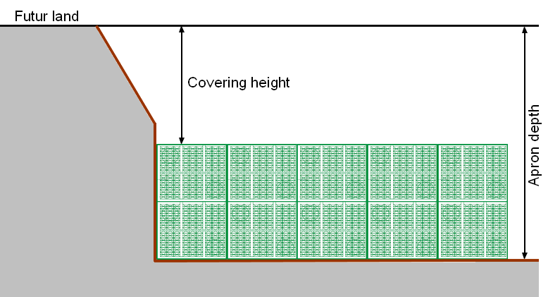
The different covering heights and apron depths are a function of the marginal conditions (e.g. intentional safety factor, density and angle of friction of the soil and filling, etc.). Covering heights up to 4 m and apron depths up to 6 m are possible.
A Rigofill Inspect® basin can be installed in a water table as long as the top layer above the modules compensates Archimedes thrust. In this case, the total watertightness of the basin must be ensured and will be executed by Canplast.
To establish the evaluation, it is necessary to have a static calculation which will be carried out by our technical department.
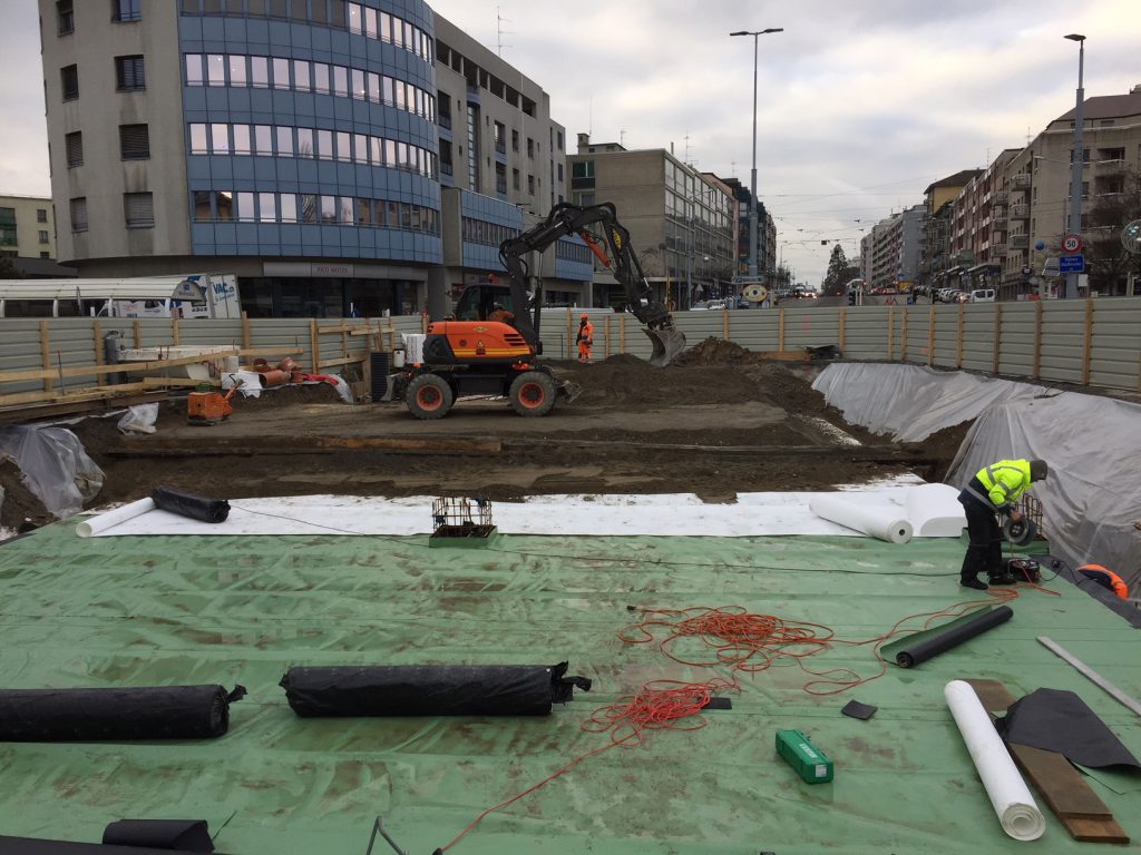
The work assigned to the company responsable for the realisation of a retention basin with Rigofill® modules, is listed below. Additional information can be found in the « Implementation » documentation below.
- Earthwork and levelling of the excavation bed.
- Supply and installation of fine gravel to precisely regulate the bottom of the excavation.
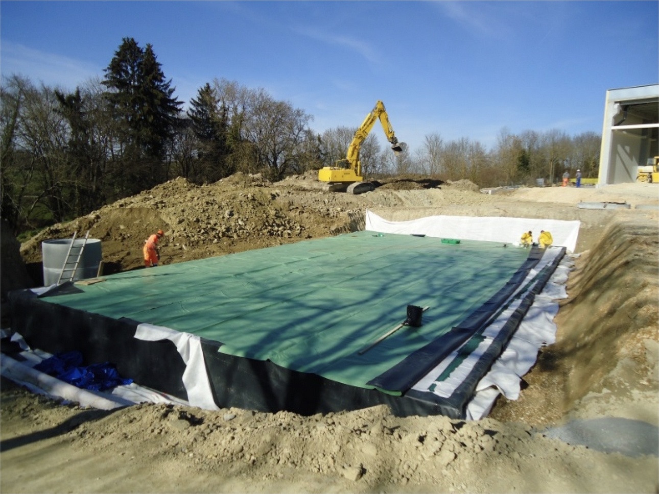
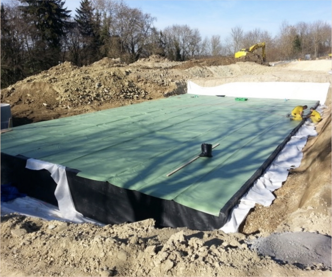
- Supply and installation of a geotextile to protect the geomembrane on the outer face.
- Laying a geomembrane under the modules and against the lateral faces of the modules, with an all-round overlap of approximately 30 to 40 cm on the upper part. The geomembrane is delivered by Canplast, already cut to the dimensions of your basin.
- Laying a second geotextile to protect the inner face of the geomembrane.
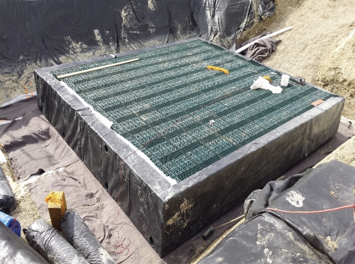
- Install Rigofill® modules (non damaged), closing plates and fixing clips.
- Reassemble the three layers (geotextile-geomembrane-geotextile) on the lateral and upper faces of the modules.
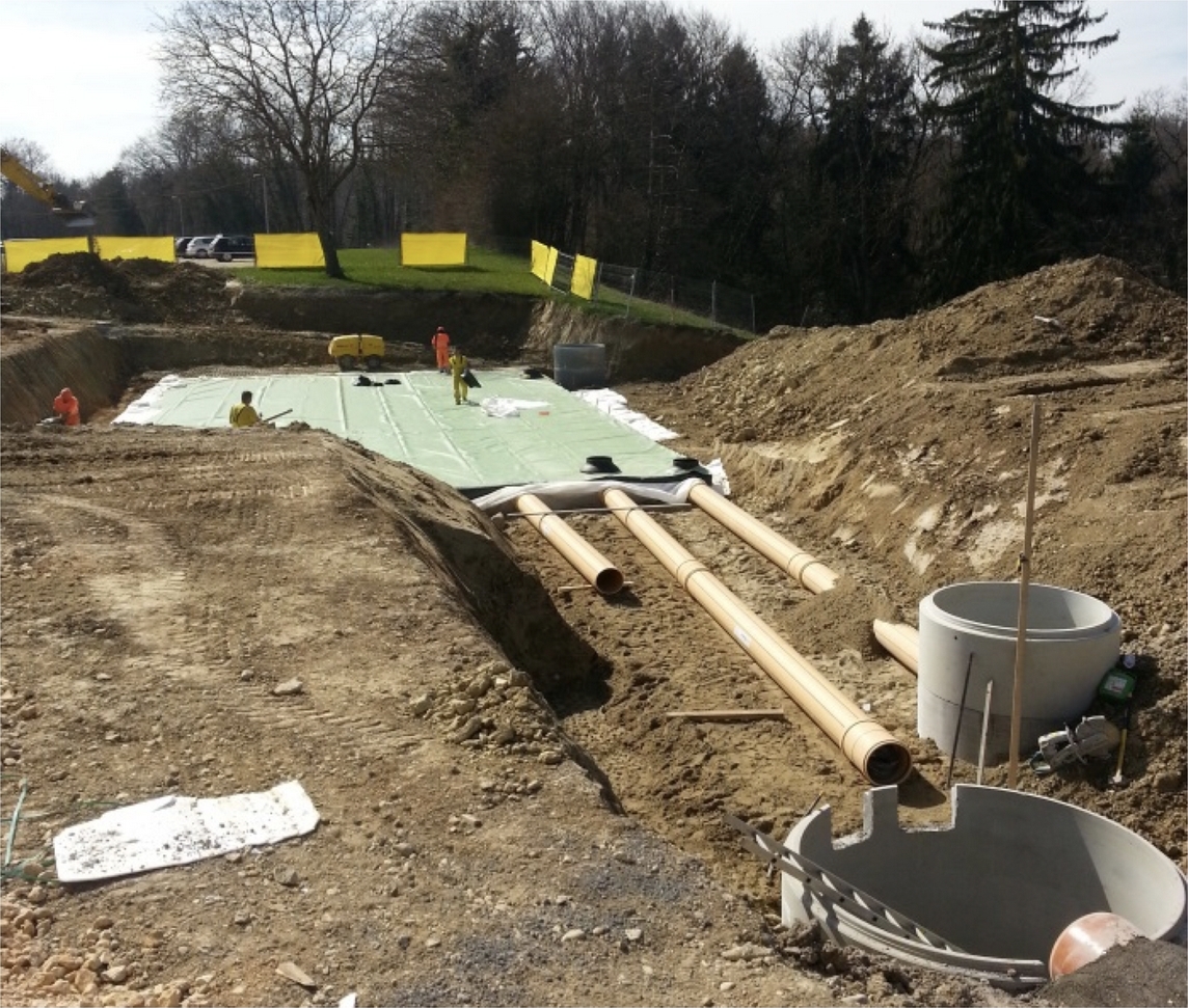
- Connecting the pipes.
- Backfilling and compaction
The work involving an infiltration basin is simpler. Indeed, the modules will be wrapped only by a woven-type geotextile the resistance and permeability of which are defined in the “Implementation” documentation below.
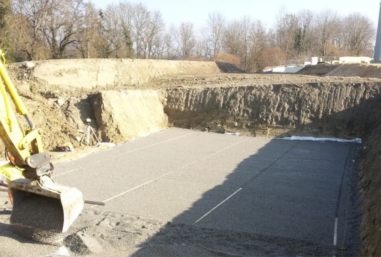
Earthwork
The general dimensions of the trench or excavation should, when possible, extend 50 cm further than the basin unit borders on each side. The characteristics of the natural ground must also be taken into account. The general dimensions of the trench or excavation must allow safe access to staff in order to ensure the implementation of the basin.
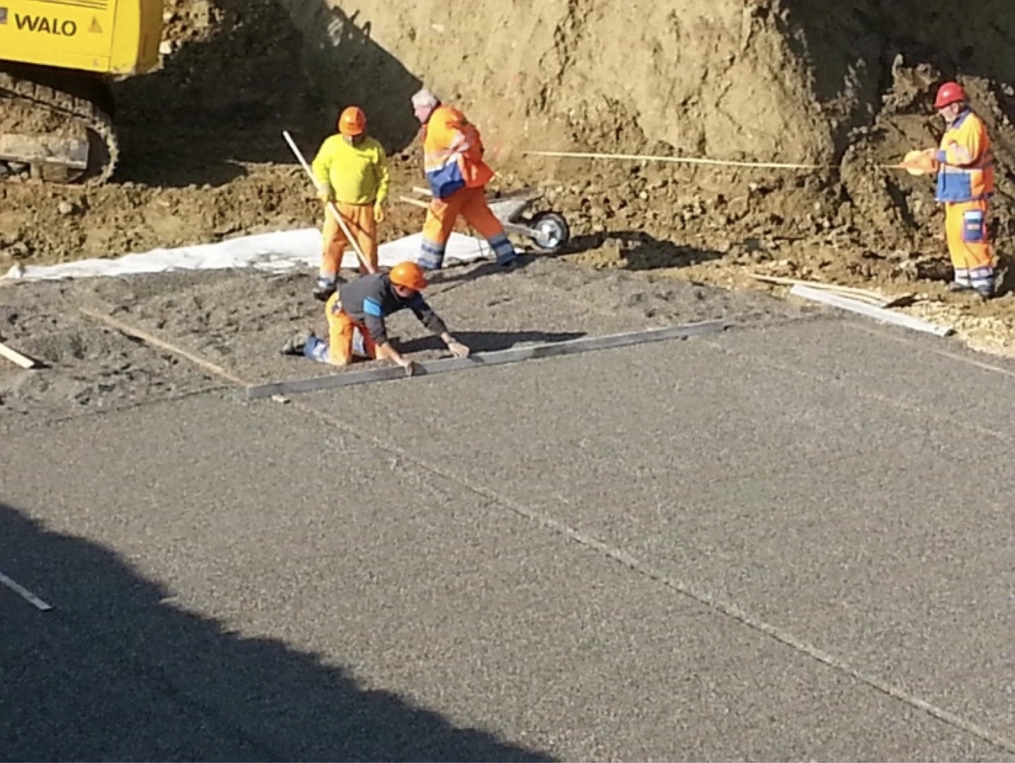
Bedding
Creation of a bedding at least 10 cm deep, respecting the following criteria :
- 95% OPN compaction below retention basins.
- At least 92% OPN compaction below infiltration basins according to the particle size and permeability of the material
- Sand or 0/32 gravel bedding, horizontal and flat, levelled with a straightedge.
- The permeability of the bedding after compaction must be at least equal to that of the ground on-location. The quality of the bedding is decisive for the implementation of the system. It has a significant impact on the strength and packing of the modules, particularly when they are superimposed or subjected to high loads. A minimum load bearing capacity of 35 MPa is required to ensure the long-term stability of the system under traffic loads.
Geotextile and/or geomembrane installation
1 - Retention basin
Installation of the geotextile (not supplied by Canplast), which will be covered by the geomembrane (made to measure and provided by Canplast). A second layer of geotextile will cover the geomembrane.
The minimum mechanical characteristics of the geotextile are as follows :
- Tensile strength : > 20 kN/m
- Static puncture : > 3.5 kN
- Hydraulic perforation : < 20 mm
- Permeability, perpendicular to the plane : > 0.02 m/s
- Filtration opening : > 63 µ et < 150 µ
The dimensions of the inner geotextile correspond to the length and width of the basin plus 50 cm on each side.
2 - Infiltration basin
Installation of the geotextile. It is recommended to use a separation-type geotextile with a flat filtration opening and a normal permeability determined in accordance with the infiltration speeds measured at the construction site. It is also recommended that the geotextile has a permeability at least 10 times greater than the geotextile of the ground on-location.
The minimum mechanical characteristics of the geotextile are as follows :
- Tensile strength : >7 kN/m
- Static puncture : > 1kN
- Hydraulic perforation : < 35 mm
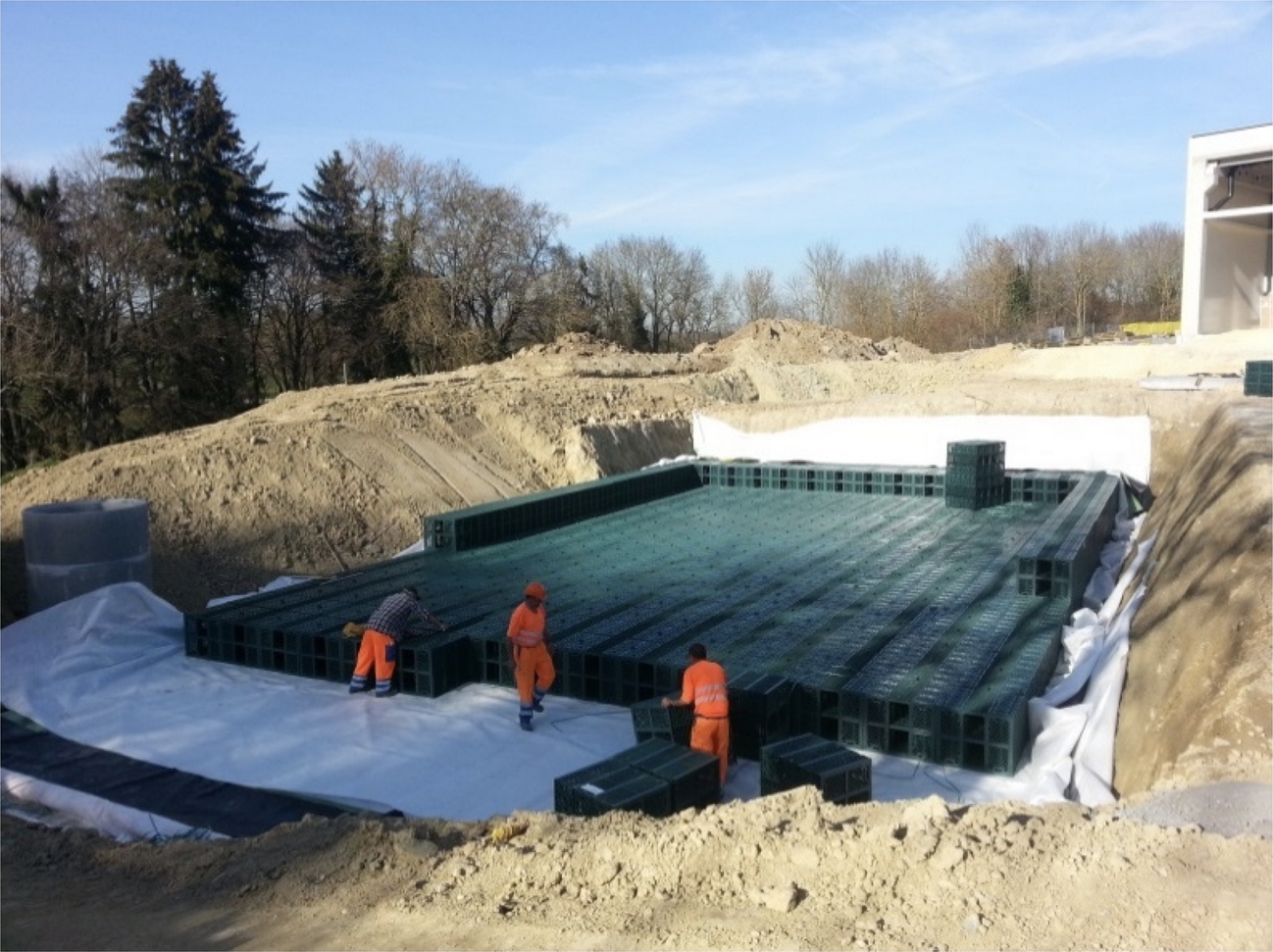
Installing the modules
Before installing the modules, ensure that the geomembrane is free of any processing waste (e.g. gravel, soil, etc.). Damaged modules must not be used to avoid the risk of tearing the geomembrane.
The modules are juxtaposed and superimposed according to the instructions below, or according to the provided layout plan. There must be no runoff or underground water at the bottom of the excavation.
- Install the modules according to the mounting direction of their inspection channels and make sure that the modules are aligned,
- lock the modules using the fixing clips in order to prevent movements. The fixing clips are located at the middle of the top edge of each module,
- place the end plates on the side faces of the modules by fitting them together. In the case of an inlet, the end plate will position itself to reach the highest water line. In the case of an outlet, the end plate will position itself to reach the lowest water line.
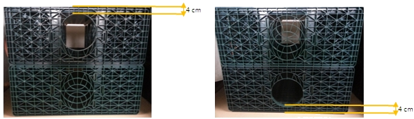
Figure 1: Positioning of the end plate for the inlet passage (left) and for the outlet passage (right)
- Build each layer of the basin using the same methodology.
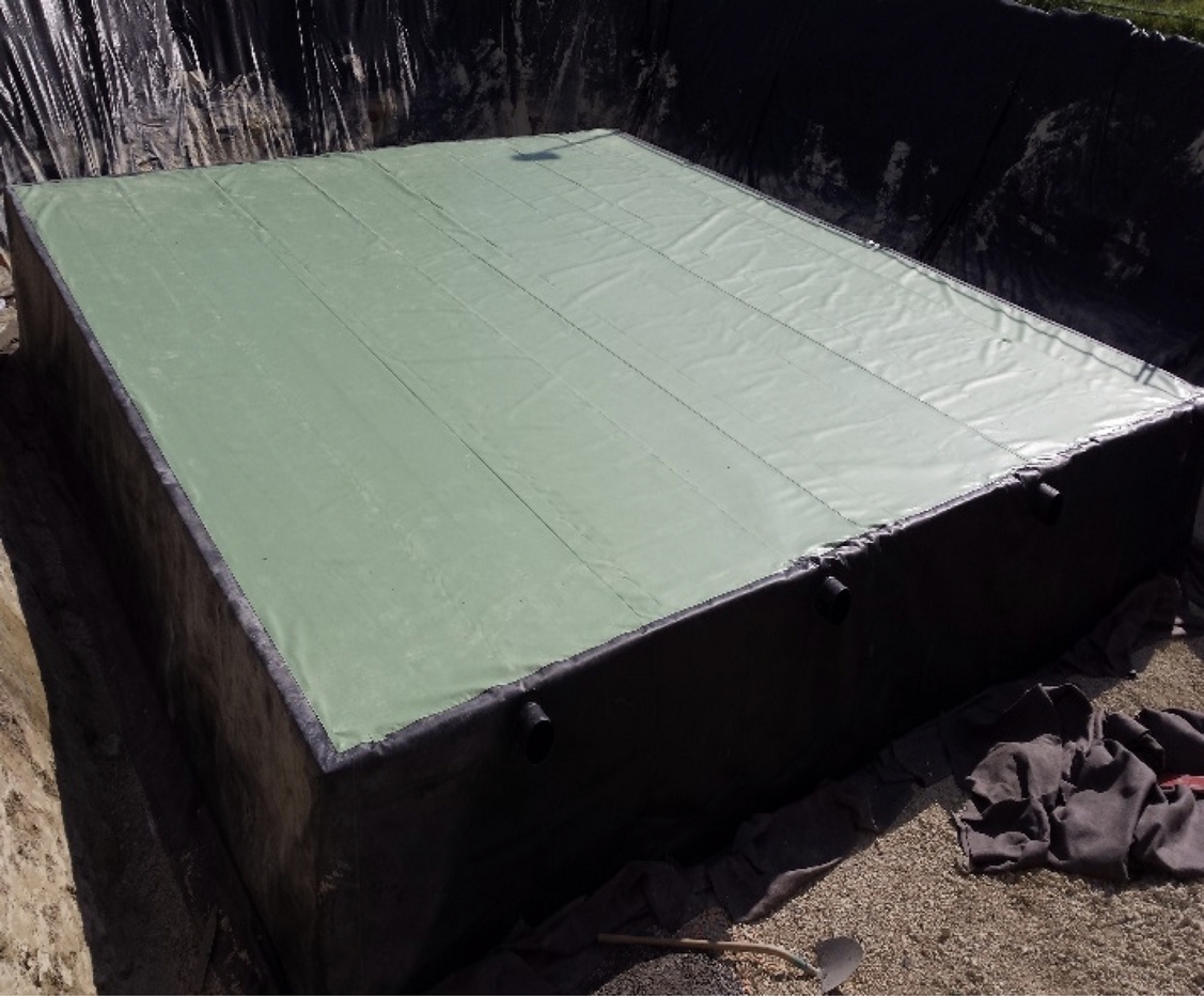
- After the completion of module assembly, fold the geomembrane over the side faces. The geomembrane covers the perimeter of the top of the basin over approximately 40 cm.
- Canplast seals passages through the geomembrane. It is also possible to achieve complete sealing of the basin. This will be executed by a qualified Canplast technician.
- A geotextile must be installed on the upper part of the basin before backfilling.
Backfilling
The backfilling of the excavation is performed according to the instructions of leaflet 70.
1 - Lateral backfilling
The quality of this backfilling is important for the long-term durability of the structure.
The work space adjacent to the infiltration or retention basin must be filled with excavated soil, free of stones and compacted in 0.3 m thick layers. The backfill should be compacted layer by layer with a lightweight - medium vibrating plate with a maximum compacting force of 3 tons.
Remarks concerning lateral backfilling :
- Do not use coarse/crushed backfill materials.
- Be careful not to damage the geotextile and/or geomembrane.
2 - Upper backfilling
The retention/infiltration structure must be covered with materials in accordance with the project characteristics. In the case of an installation under roadway or under parking, it will be surmounted by a roadway structure accordingly. The following table, for information purposes, illustrates the necessary backfilling heights for specific loads.
| Green area | Parking area | Heavy traffic area | |
| Roadway structure: base, foundation layers and surface course | Minimum 0.25 m | Roadway structure | |
| Upper backfilling: subgrade |
≥ 15 cm of sand 0/32 | ≥ 50 cm of sand 0/32 or ≥ 65 cm of sand 0/32 Depending on traffic class |
|
| SAUL (Module) | Module structure | ||
| Bedding | 10 cm depth of sand or gravel 0/32 | ||
The different points to be taken into account during the upper backfilling are as follows :
- A protective layer of 10 cm of sand should be applied on the top of the modules wrapped by the geotextile. The thickness of the first layer of backfill will be determined according to the compacting machine and the mechanical behaviour of the modules (short-term compressive strength). Its minimum thickness should be 25 cm compacted.
- Backfill over the basin in compacted layers of 30 cm (or adapt according to the compaction machine).
- Use light shovels or loaders (maximum total weight 15 t) in order to distribute the backfill.
- For the construction of the backfill, allow a protective height that takes into account the power of the compaction machines in order to preserve the integrity of the basin.
- Make a compacted backfill of a minimum height of 50 cm before construction vehicles (<15 tonnes/axle) can circulate over the structure.
- Under green areas, a minimum compacted thickness of 0.25 m will be required
- Do not drive on the structure before backfilling and compaction.
Tips and recommendations
We cannot advise a frequency of inspection or cleaning as the conditions vary according to the place of installation. Each project is specific.
To prepare for your basin maintenance, we recommend the following actions:
- An inspection and hydrocleaning of the distribution or settling structures positioned upstream of the basins (if installed) after the completion of the construction phase.
- An inspection and hydrocleaning of Quadro-control® manholes after the completion of the construction phase. These will indicate to you the necessity or not of a hydrocleaning. A camera passage is recommended to check the correct placement of the structure elements. (If the tunnel is somehow displaced or in a staircase shape, such an inspection would alert us of an installation problem).
- After this inspection, we recommend an additional visual inspection after 6 months. Only then, a decision can be made whether it is necessary or not to undergo further inspections or proceed with hydrocleaning. If no further operation is necessary, we can space the controls to 12 months until the right frequency is found.
- In all cases, we advise a careful control and maintenance of the decantation structures and upstream screens. These structures guarantee the sustainability of your basins.
- Do not forget the regular control and cleaning if necessary of the flow limitation structures.
- After a major climatic event (e.g. heavy storm), we recommend an inspection and a hydrocleaning of the structure.
- The cleaning pressure will be limited to 125 bars. The recommended tool must have a rotating round head. Tools that can damage the structure (notched heads) must not be used.
Access to the structure and cleaning
The inspection tunnels and their access points by the Quadro-control® manholes or the downstream chamber are identified on the map. The basin layout plans and the layout plans provided by Canplast must be accessible and transmittable to the maintenance teams and all the requesting parties.
Inspection and/or cleaning will be by access of the Quadro-control® or the downstream chamber to accessible inspection tunnels.
Dimensions of access structures and tunnels
- Diameter of the manhole extension : 500 mm
- Manhole size: W/L/H= 80/80/66 cm
- Manhole maximum depth : _______ m
- Tunnel section W/H = 22/27 cm
- Section passage manhole - tunnel W/H = 21/21 cm
The inspection of the tunnel will be done using a self-propelled waterproof camera, with adjustable remote control and will have to correspond in terms of dimensions to the material suitable for inspection of DN 200 pipes.
For multilayer systems, only tunnels at the lowest position of the blocks will be inspected.
Eventual hydrocleaning must be done with standard equipment.
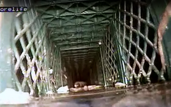
Figure 1: Inspection before cleaning Rigofill® Modules containing large amount of macro-waste (dirty basin)

Figure 2: Post-cleaning inspection (clean basin)
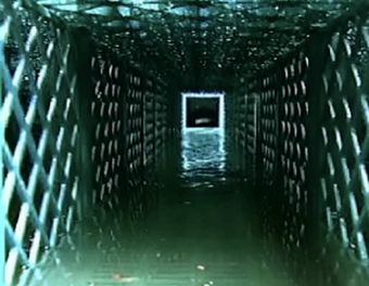
Figure 3: Inspection of a Rigofill® basin after hydrocleaning via the cleaning passage
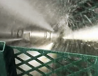
Figure 4: Hydrocleaning inside inspection tunnels
| 1. Description | Retention/infiltration module with inspection channel for installation of an underground retention and infiltration system |
| 2. Material | Polypropylene PP – Green colour |
| 3. Dimensions / weight | Module : 800 x 660 mm - Weight : 20 kg Half-module : 800 x 800 x 355 mm - Weight : 12kg |
| 4. Storage capacity | Gross volume : chamber 4221 l/ half-module 224 l Storage volume : module 400 l/ half-module 221 I Working volume : 95% |
| 5. Covering and roads | Maximum coverage : 4 M (under conditions) Maximum depth of installation, height of chambers and embankment : 6 M (under conditions) Thickness of road to be implemented according to class of traffic, consult our implementation requirements |
| 6. Long-term verification | Structural analysis according to the FEM method Long-term test guaranteeing product behaviour extrapolated to 50 years |
| 7. Connecting blocks | Horizontal and vertical with block fittings (assembly clips) |
| 8. Inspection tunnel | Tunnel that allows perfect inspection and control of infiltration zones (geotextile) and parts of the structur |
| 9. Quadro-control® manhole system | Integration into the Rigofill Inspect® system because it has the same geometry as a single chamber Extension interior diameter : 500 mm |
| 10. Connection system | Smooth pipe Ø 110, 160, 200, (250, 315 optional) directly on modules Smooth pipe Ø 200 to Ø 600 on the Quadro-control® manhole (on demand) |
| 11. Ventilation of the structure | By Quadro-control® and ventilated top It is not necessary to have a separate ventilation adapter |
| 12. Quality check | Permanent equipment and tests carried out on the chambers |
| 13. Installation | Installation according to prescription of implementation |