Since March 2010, Canplast has been distributing Saint Dizier environnement products in Switzerland.
With more than 40 years of experience, Saint Dizier environnement, is a leader in the design and supply of turnkey structures for road, urban and industrial rainwater treatment, as well as hydraulic control structure.
Applications
Stormwater treatment system meeting the increased requirements for stormwater treatment in Switzerland (Federal Ordinance on Water Protection (OEaux) and VSA Directive "Evacuation of rainwater").
Characteristics
Saint Dizier environnement has been present in Switzerland for more than 20 years and has several reference achievements for the treatment of surface water, with treatment rates up to 1'000 l/s (e.g. Geneva International Airport, A9 motorway - State of Valais).
Range
- S235 steel lamellar separator protected by a heat-cured polyurethane coating
- Polyester lamellar separator
- Rehabilitation of existing concrete structures
Desanders hydrocarbon separators
(french PDF files to download)
Steel
Polyester
Improved performance of settling basins in civil engineering with optimised lamellar settling.
Summary
The Saint Dizier environnement company installed runoff settling basins on the A9 motorway in Switzerland in 2011. The work consisted in sizing and making improvements to the existing settling structures, in order to improve their purification performance by the implementation of alveolar settling structures. A fall rate of less than 3 m / h was chosen for the design. Nearly two years after this work, an evaluation of the performances of two structures was carried out: Sablons, and Ile d'Epine. A particle size analysis revealed the efficiency of lamellar settling: 50% of the particles have a diameter of less than 19.2 μm. The sludge was loaded with hydrocarbons and pollutants (PAH, heavy metals). The audit-sizing and design-basin layout methodology is reproducible for all structures, both in construction and rehabilitation.
Introduction
1 - Project display
Eleven roadway water treatment works on the A9 motorway upstream of infiltration basins no longer met the requirements for water protection. Saint Dizier environnement was therefore mandated in 2010 by the client to audit the structures in place in order to carry out a technical proposal to improve purification performance.
The A9 motorway crosses the southwestern quarter of Switzerland, between France and the Simplon Pass. The sections concerned are located near Saint Maurice and Evionnaz. The average daily traffic in this zone was 37,300 vehicles in 2014 according to the Federal Office of Roads (FEDRO). This article focuses on the Ile d'Epine and Sablons basins.
2 - Characteristics of the Ile d'Epine and Sablons basins
The Ile d’Epine basin treats runoff from the motorway at kilometre 61.74 and has an area of 1.5 ha. Road water is collected by gutters along the road and then channelled to the treatment plant.
The Les Sablons basin, located at kilometre 65.95, treats stormwater from a surface of 4.5 ha. Rainwater is discharged from the roadway to ditches (retention-filtration ditches) along the road, allowing the infiltration of water and its drainage to a collection pipe that conveys the water to the treatment structure.
| Name | Ile d'Epine | Sablons |
| Location | 61.74 | 65.95 |
| Inlet DN | 800 | 1'000 |
| Gradient (mm/m) | 6 | 2 |
| Watershed surface area (ha) | 1.5 | 4.5 |
| Basin width (mm) | 2'600 | 3'600 |
| Total interior length (mm) | 10'950 | 10'650 |
| Selected treatment flow rate (l/s) on the basis of existing works and bibliographic data on rainwater |
267 | 309 |
| Presence of an excess overflow evacuation | Upper overflow | Upper overflow |
| Plenum length (mm) | 2'100 | 1'850 |
| Lamellar structure length (mm) | 7'250 | 7'500 |
Table 1: Characteristics of the two studied projects
3 - Specifications
The main criteria to be respected for the specifications are as follows:
- Motorway rainwater effluents,
- Target abatement on suspended solids > 60% of particles with a diameter of less than 50 μm,
- Target abatement on suspended solids > 95% of particles with a diameter greater than 100 μm.
Rehabilitation of structures with lamellar settling system
1 - Sizing
The dimensional criteria are as follows:
- Counter-current decantation on lamellar honeycomb structures, with a hydraulic diameter of 20 mm,
- fall rate of the SS, criteria relating to the lamellar surface necessary to obtain the performances on the SS parameters but also COD, BOD5, metals and hydrocarbons, retained at a maximum value of 3 m/h at the maximum treatment flow rate,
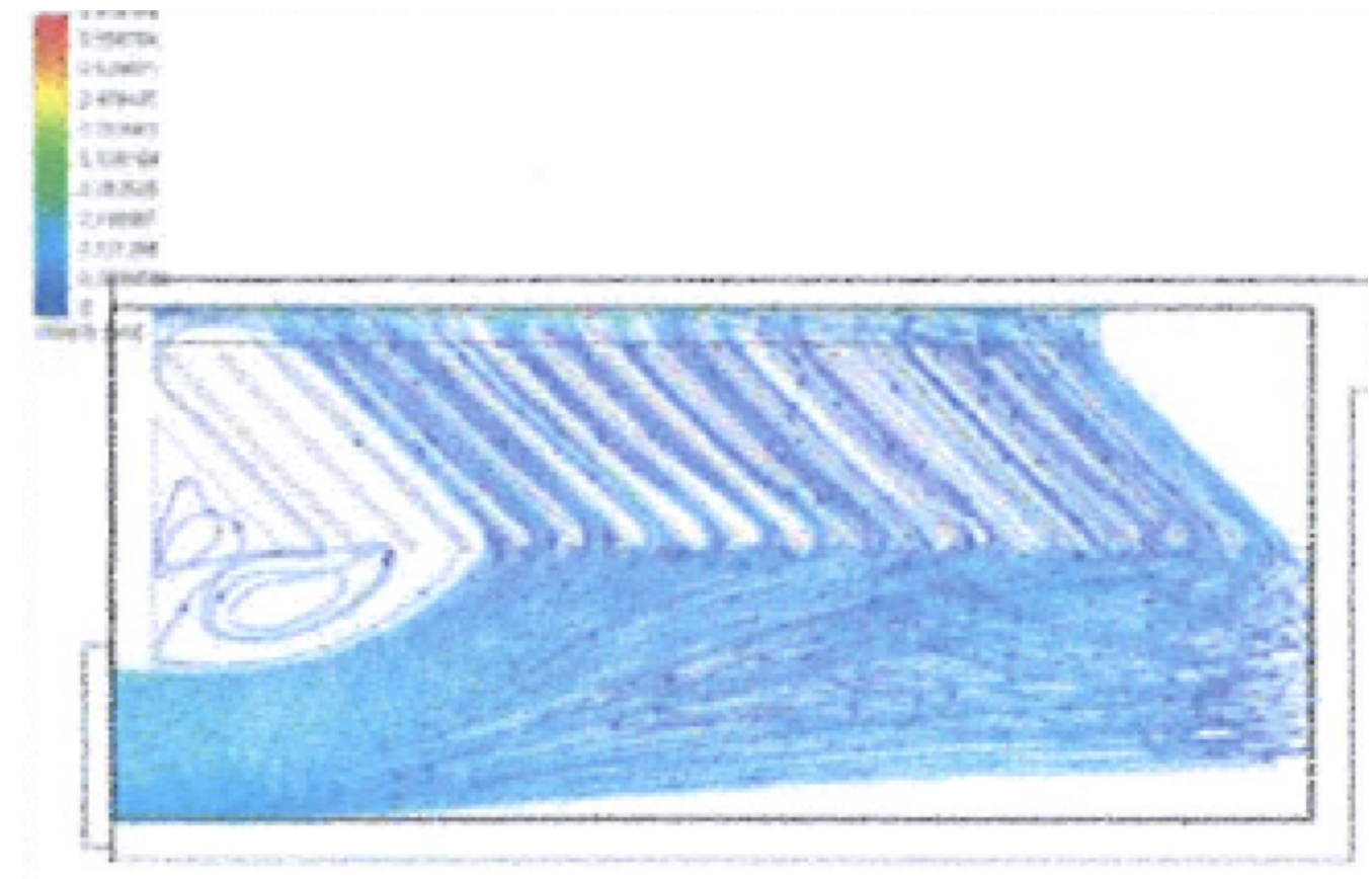
- respect of the hydraulic criteria: equi-distribution of the waters on the honeycombs lamellar structures by modelling and calculations, Reynolds number, height under cells...,
- channels for recovery of decanted water,
- consistent sludge retention, with respect to optimal utilisation of the structure: silo for sludge storage integrated in the treatment plant, regular flushing by hydrocleaning, with autonomy longer than one year.
2 - Characteristics of lamellar settling systems after rehabilitation
The basins in civil engineering were rehabilitated in 2012, with the technical data specified in the following table:
| Name | Ile d'Epine | Sablons |
| Location | 61.74 | 65.95 |
| Projected area of honeycombs (m2) | 463 | 485 |
| Actual fall rate (m/h) | 2.1 | 2.3 |
| Working volume (m3) | 64.1 | 65.6 |
| Plenum volume (m3) (2) | 12.3 | 11.4 |
| Separation volume (m3) (1)-(2) | 51.8 | 54.2 |
| Height under cells (mm) | 1'145 | 822 |
| Maximum sludge level (mm) | 460 | 250 |
| Total sludge storage volume (m3) | 14.7 | 14.8 |
| Reynolds number | 218 | 176 |
Table 2: Characteristics of lamellar settling systems after rehabilitation
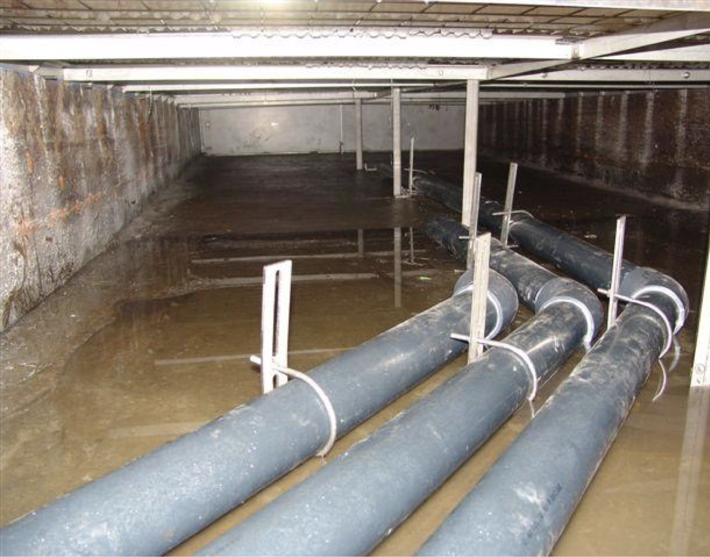
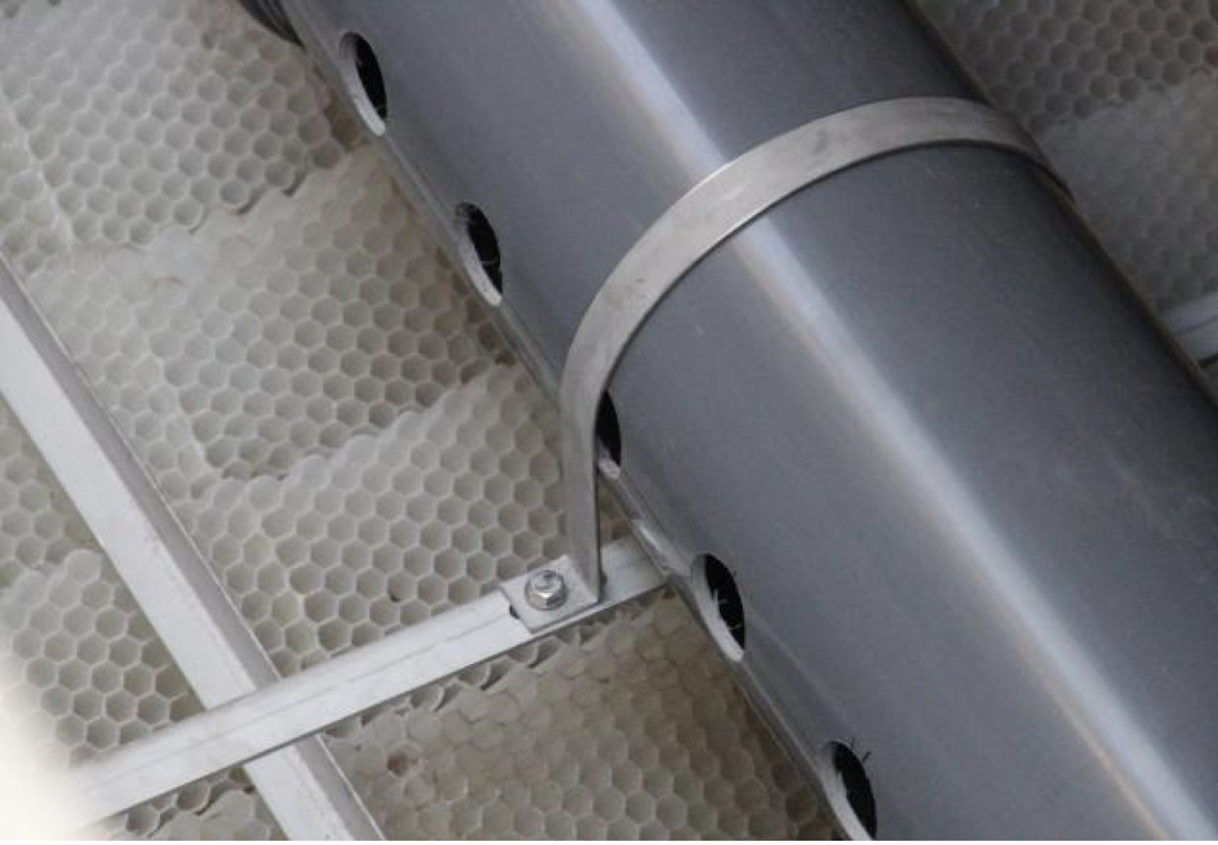
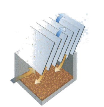
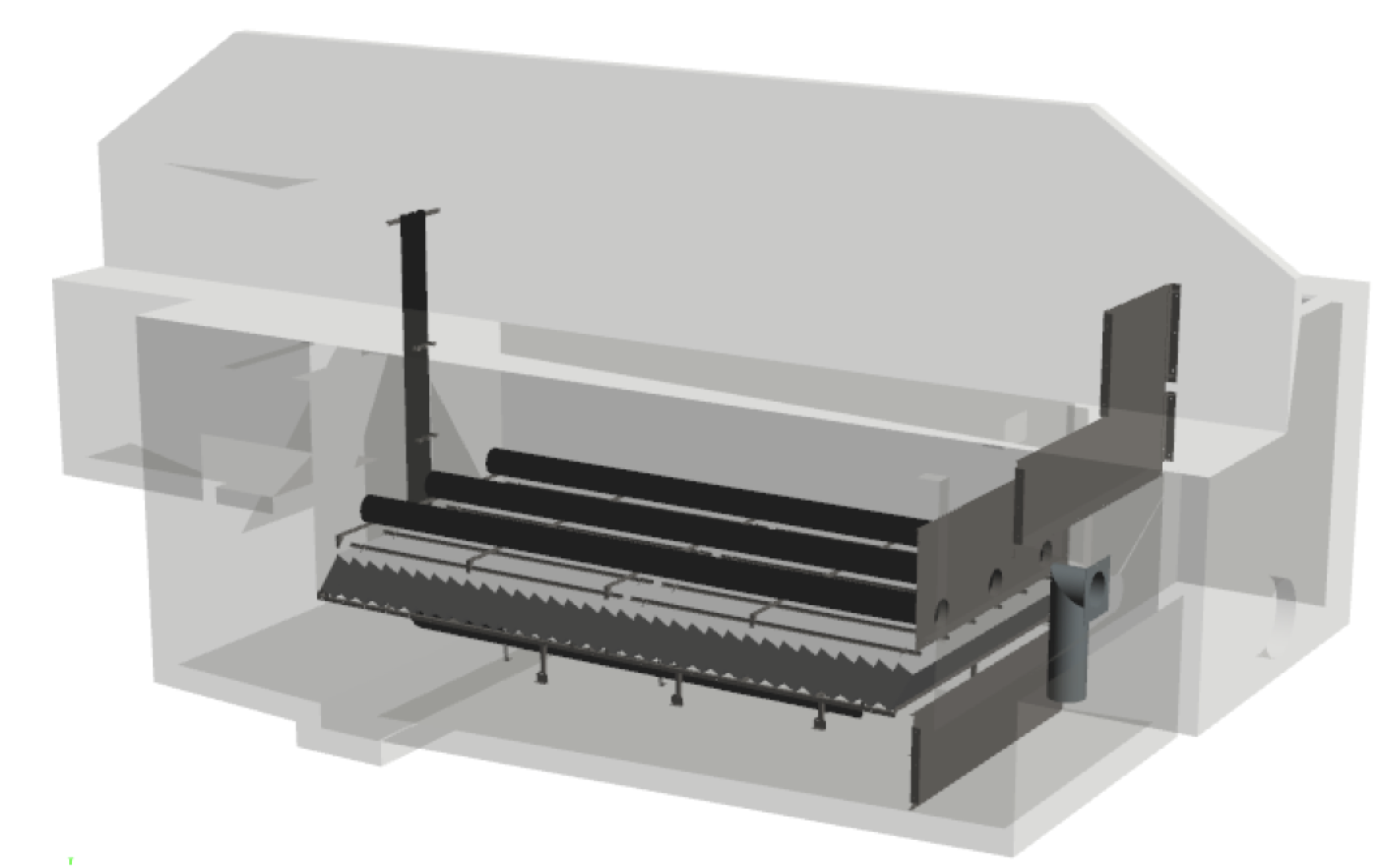
The rehabilitation works (Figure 1) consisted of:
- Building stainless steel partitions,
- creating a floor for lamellar honeycomb structures,
- laying the lamellar honeycomb structures, and their fixing devices,
- installing channels for recovery of decanted water.
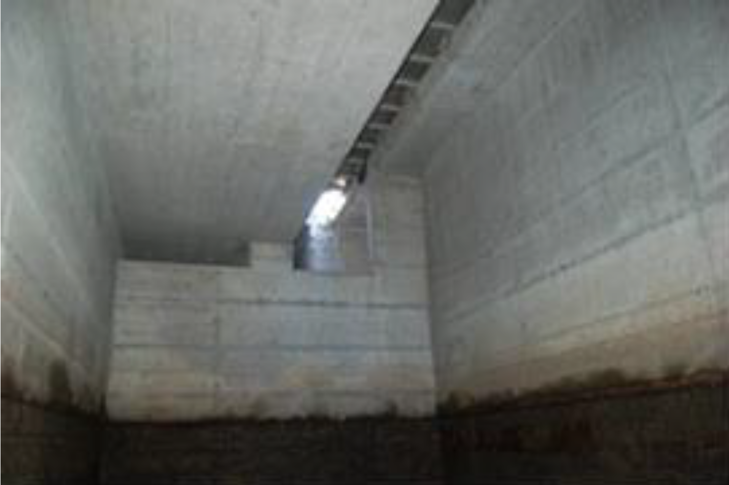
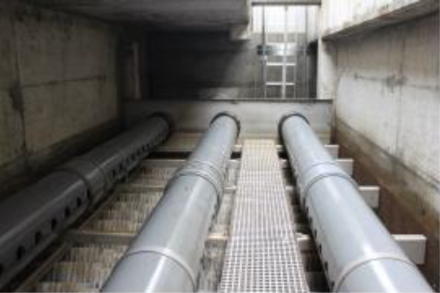
Figure 1: Before and after the installation of basins with lamellar settling systems
Analytical and qualitative assessment two years after commissioning
1 - Quantification and qualification of trapped pollutants
Samples were taken to control the volumes and masses of pollutants trapped after 2 years of operation, during the draining of these basins. The draining and sampling operations of 9 and 10 September 2014 consisted of:
- Evacuating surface water (visibly clean, analyses carried out), downstream of the structure, therefore in the natural environment,
- pumping the loaded water at the bottom of the structures (pit with over-depth), to allow access to the beds of sludge present at the base of the structure, and to ensure the samples taken,
- pumping and evacuating sludge to a treatment centre,
- cleaning with a high-pressure lance, the equipment of the structure, and in particular the lamellar structures, directly from the natural ground, then bridges placed above the lamellar structures,
- pumping the rinsing water.
The samples were taken in dry weather, the previous rainfall going back two days:
| Bassin | Sample type |
| Ile d'Epine | Sludge in plenum chamber |
| Ile d'Epine | Sludge in lamellar settling chamber under alveolar structure |
| Les Sablons | Outlet water |
| Les Sablons | Sludge in lamellar settling chamber under alveolar structure |
Table 3: Sampling taken in the basins in September 2014
The following pollutants have been identified in the settling systems:
- Floating solids,
- sludge resulting from the decantation of the SS (suspended matter).
The basins have plenum chambers upstream of the cells:
- The Ile d'Epine plenum chamber had about 40 cm of coarse and relatively solid sludge and waste.
- Upstream of Les Sablons basin, there is a retention-filtration channel which ensures the first decantation of the effluents. Very little sludge was in the plenum chamber of Les Sablons basin. It had a finer aspect, liquid and fairly homogeneous for the entire basin.
| Lamellar settling system | Ile d'Epine | Les Sablons |
| Sludge level in plenum chamber | 40 cm | 10 cm |
| Sludge volume in plenum chamber | 2.1 m3 | 0.67 m3 |
| Sludge level in lamellar settling chamber under cells | 9.5 cm | 10 cm |
| Sludge volume under cells | 1.8 m3 | 2.7 m3 |
Table 4: Quantity of sludge in basins
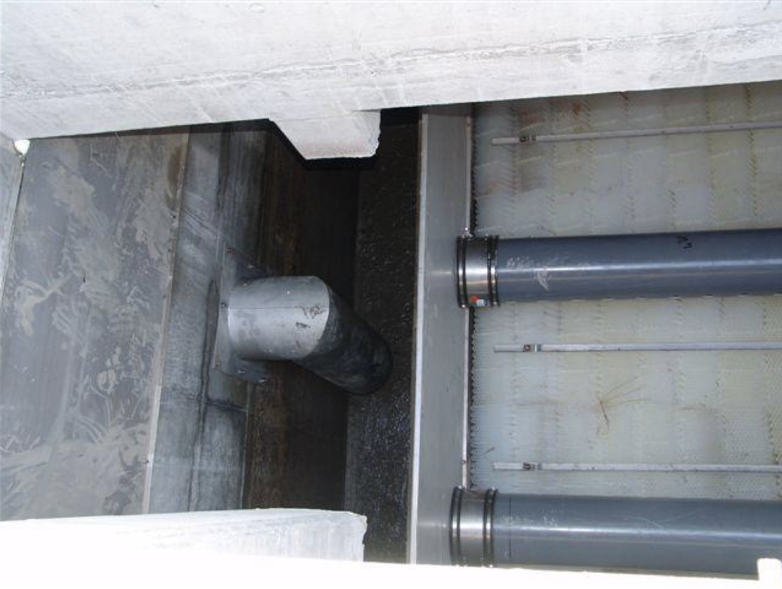
The sludge observed and measured under the cells is mainly related to fine particles. The largest particles are in fact retained upstream of the lamellar blocks (networks, ditches, plenum chamber (see Figure 2)).
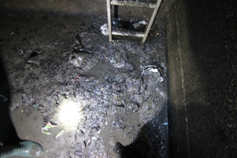
Figure 2: Trapped pollutants in Sablons basin plenum chamber
Table 5 expresses the annual flows of suspended solids for each of the watersheds, based on experimentally determined sludge volumes and measurements taken on the dryness and density of the sludge located in the plenum chambers and under the lamellar cells.
| Basin | Ile d'Epine | Les Sablons |
| Watershed surface area (ha) | 1.5 | 4.5 |
| Sludge volume in plenum chamber (m3) | 2.1 | 0.67 |
| Sludge dryness (%) | 75.6 | 76 |
| Average sludge density | 1.5 | 1.5 |
| Suspended solid flow in the plenum chamber (kg/ha/year) | 794 | 85 |
| Sludge volume under cells (m3) | 1.8 | 2.7 |
| Sludge dryness (%) | 29.7 | 50 |
| Average sludge density (estimated) | 1.3 | 1.3 |
| Suspended solid flow under cells (kg/ha/year) | 232 | 195 |
| Suspended solid cumulated flow (kg/ha/year) | 1'026 | 280 |
Table 5: Determination of suspended solids annual flows for each watershed
The literature (CLT12) gives an average annual flow of SS per hectare of between 500 and 1,200 kg/ha/year, for road-type watersheds with high traffic.
The results obtained for the Sablon Basin are lower than the values of the literature. The retention-filtration channel upstream of this basin retains an important part of the SS; the results obtained are therefore consistent with the literature.
The results obtained for the Ile d'Epine basin are consistent with the average values of the literature.
This is a sample text. You can click on it to edit it inline or open the element options to access additional options for this element.
A particle size analysis of the sludge under the lamellar structures from the settling chamber of the Ile d'Epine basin was carried out by laser by a COFRAC approved laboratory. The results are shown in Figure 3, which highlights the very small size of the intercepted particles:
- 10 % of the particles are less than 3.5 μm,
- 50% of the particles are less than 19.2 μm, which corresponds to the average diameter,
- 75 % of the particles are less than 44.4 μm,
- 90 % of the particles are less than 98.4 μm.
This is a sample text. You can click on it to edit it inline or open the element options to access additional options for this element.

This is a sample text. You can click on it to edit it inline or open the element options to access additional options for this element.
The presence of such fine particles is explained by the retention of larger particles upstream of the lamellae in the plenum chamber. The trapping of the fine particles results from the low surface hydraulic load of the lamellar settling system. This hydraulic load is 2.1 m/h for a treatment flow of 267 l/s, but the great majority of the rain leads to lower flow rates, and therefore to much lower surface hydraulic loads, guaranteeing very good performance interception of suspended matter. The level under cells is important, and also guarantees flow rates of the effluent between the sludge bed and the lower part of the cells without displacement previously trapped sludge.
This is a sample text. You can click on it to edit it inline or open the element options to access additional options for this element.
The sludge from the plenum chamber (Ile d'Epine) and the chambers beneath the lamellar honeycomb cells were also analysed; the results are shown in Table 6.
This is a sample text. You can click on it to edit it inline or open the element options to access additional options for this element.
| Parameters | Analysis method | Units | Ile d’Epine plenum chamber | Ile d’Epine lamellar settling chamber | Les Sablons lamellar settling chamber |
| Dry matter | ISO 11465 (A) | % mass MB | 75.6 | 29.7 | 50.1 |
| COD (homogenised) | ISO 15705 (A) | mg/kg MS | 230 | 6'600 | 1'700 |
| Hydrocarbon index (C10-C40) | EN ISO 16703 (A) | mg/kg MS | 700 | 1'600 | 560 |
| Zinc | EN ISO 17294-2 (A) | mg/kg MS | 490 | 1'300 | 490 |
| Cadmium | ISO 18287 (A) | mg/kg MS | <0.5 | 0.5 | <0.5 |
| Lead | ISO 18287 (A) | mg/kg MS | 16 | 65 | 37 |
| Added PAH | ISO 18287 (A) | mg/kg MS | 0.77 | 5.3 | 0.16 |
Table 6: Pollutants present in the sludge of both lamellar settling systems
This is a sample text. You can click on it to edit it inline or open the element options to access additional options for this element.
There is a percentage of dry matter entering the basin of Ile d'Epine larger than at the output. This is because the larger particles settle earlier in the basin than the smaller ones, usually with lower dryness.
There is also a much higher proportion of pollutants (COD, hydrocarbons, metals and PAH) retained per kilogram of dry matter in the lamellar settling chamber under the cells than in the plenum chamber. The explanation lies in the fixation of these substances on the smallest particles.
Sludge from lamellar settling chambers is much more polluted in the Epine Island watershed than Sablons, with COD and hydrocarbon concentrations 3-4 times higher and up to 30 times higher for PAH, without any real explanation, except perhaps for larger amounts of hydrocarbons.
2 - Operations of the structures
The basins along the motorway are easily accessible with a possible parking near the settling systems for a hydrocleaning machine.
The water under the surface of the basins is pumped and discharged to the natural environment. The analyses carried out demonstrate the good quality of this settled water (see Table 7).
| Parameters | Analysis method | Units | Les Sablons clean water |
| SS | EN 872 (A) | mg/L | <5 |
| COD (homogenised) | ISO 15705 (A) | mg/L | <15 |
| Hydrocarbon index C10-C40 | EN ISO 9377-2 (A) | mg/L | <0.05 |
| Zinc | EN ISO 17294-2 (A) | μg/L | <50 |
| Cadmium | EN ISO 17294-2 (A) | μg/L | <1.5 |
| Lead | EN ISO 17294-2 (A) | μg/L | <10 |
| Conductivity | EN 27888 (A) | μS/cm | 170 |
| pH | 7.4 to 14.5°C |
Table 7: Analysis of the clear water discharges of the Les Sablons basin
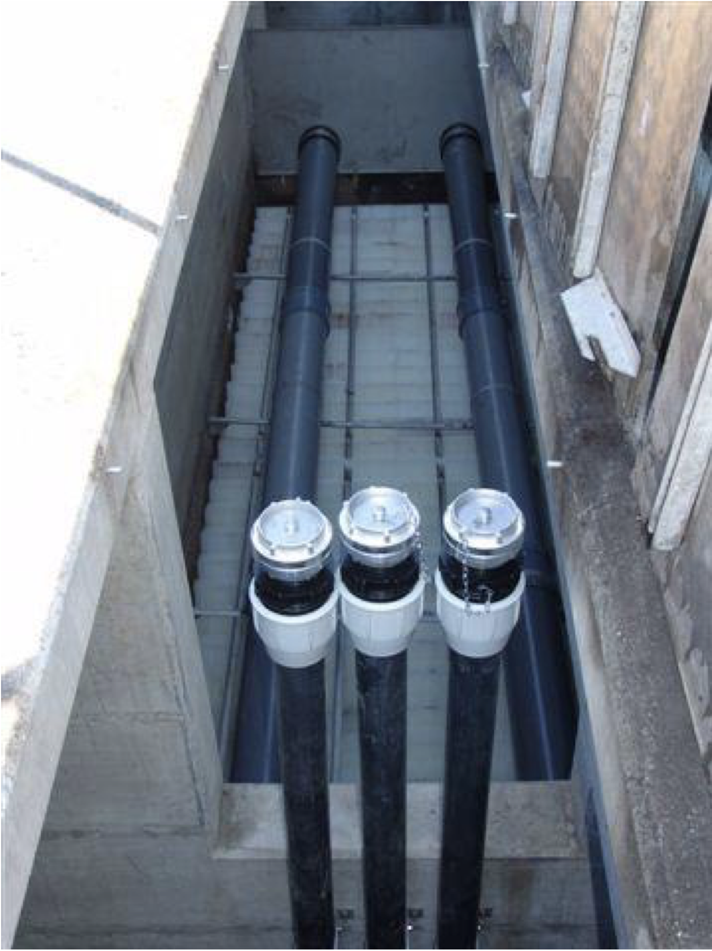
The sludge is sucked by an emptying truck, then the lamellar cells are cleaned by a high-pressure lance (see Figure 4). The duration of this intervention per basin is approximately two hours, or about half a day per basin with the emptying and the re-filling with clear water.
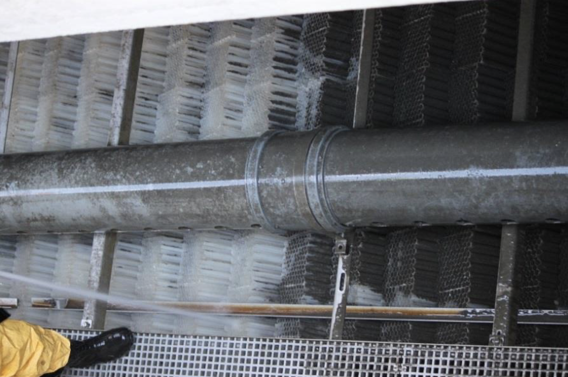
The maintenance operations of these structures equipped with honeycomb lamellar cells have been carried out under very good conditions, with remarkable efficiency for the cleaning of the settling cells and a duration of intervention deemed effective by the actors present during these operations, considering the dimensions of the structures.
It should be noted that regular monitoring of these structures, with regular visual inspections and sludge height measurements, is the key to a successful, cost-effective operation, with efficient structures.
Conclusion and perspectives
The rehabilitation study for Ile d'Epine and Les Sablons basins made it possible to obtain a custom-made solution adapted to the configuration of each basin. The equipment of these basins has been optimised with a superficial hydraulic load of less than 3 m/h.
The basins were equipped in 2012. After 2 years of operation, the structures were emptied and samples were taken.
The analyses put forward a very small particle size for the Ile d'Epine basin (d50 = 19.2 μm), which indicates a good efficiency of the lamellar settling system.
The development of civil engineering structures makes it possible to use the already existing infrastructures, while significantly improving their performance. The cost/performance ratio is then optimal.
This work and the monitoring carried out have allowed us to explore new development axes, in order to further facilitate the operation and maintenance of these underground structures.
Bibliography
CLT12, rain water management and treatment; Techni.Cités publishing
Many concrete structures in operation for several decades are present on the rainwater networks. These structures no longer meet current standards and are obsolete. With the technology we offer, these structures, in some cases, can be rehabilitated to meet the new requirements.
Characteristics
Depending on the hydraulic and geological characteristics, a technical proposal will be sent to you to meet the discharge standards.
In many cases, counter-current lamellar settling on lamellar structure is used. This process ensures a perfectly controlled settling thanks to a perfectly laminar flow. The sludge is trapped on the undersides of the honeycomb structures, and slides naturally to the sludge silos beneath the lamellar structures.
A siphon located downstream of the structure allows the retention of light hydrocarbons.
Study and design
The figures below represent a concrete structure rehabilitated with the "counter-current lamellar settling” technology. The watershed size was 4.5 ha with a traffic area of around 20'000 vehicles/day. The expected treatment rate is 254 l/s.

Illustration
The images below represent real projects.