Static calculation
The static calculation, carried out according to the SIA 190 standard, checks the structural safety as well as the serviceability and takes into account the rigidity of the system, the characteristics of the construction materials, the encasement profile and the loads exerted.
- Terrain deformation module: 3 N/mm2
- Volumetric mass density of the ground: 20 kN/m3
- Support factor for flexible hose: 1.2
- Dynamic coefficient: 1.3
- Plastic pipe diameter: Ø 250 mm
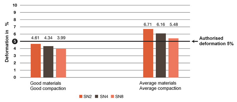
The importance of compaction (examples)
The influence of terrain quality and compaction is shown below. The calculation of the deformations was carried out according to the SIA 190 standard.
In the case of a good material and a good compaction, the pipe having the lowest rigidity (SN2 in this case) is allowed. For average material and compaction, the pipe with the highest rigidity (SN8 in this case) will not be allowed. The quality of the material and the compaction strongly influence the result of deformation.
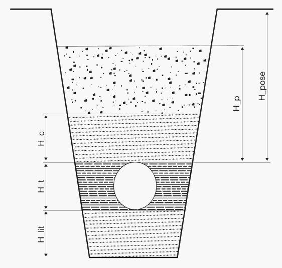
Depth of laying
The installation depths of the PVC, PE and PP pipes meet the criteria of the SIA 190 standard, in order to guarantee the structural strength and a maximum admissible deformation of 5% of the plastic pipes. According to standard SIA190, the minimum covering height (H_pose) is 0.8 m.
The tables below define the allowable installation depths (H_pose), as an indication, depending on the type and rigidity of the pipe, the load profile and the quality of the encasement.
Recommended installation depth for PVC pipes. Eshort=3'600N/mm - Elong=1'750 N/mm
Reference
height
H_pose
in m
|
|
HARD PVC PIPES
COMPACT
|
|
HARD PVC PIPES
COMPACT
|
|
Loads OUTSIDE traffic areas
Load Model 1 SIA 160
|
Loads INSIDE traffic areas
Load Model 3 SIA 160
|
|
U1/V1 PROFILE
|
U1/V1 PROFILE
|
|
SDR 51
(S 25)
SN 2
|
SDR 41
(S 20)
SN 4
|
SDR 34
(S 16.5)
SN 8
|
SDR 51
(S 25)
SN 2
|
SDR 41
(S 20)
SN 4
|
SDR 34
(S 16.5)
SN 8
|
|
|
|
|
|
|
0.50
|
|
|
|
|
|
|
|
0.60
|
|
|
0.65
|
|
|
|
|
0.70
|
|
0.75
|
|
|
|
0.70
|
|
0.80
|
0.80
|
|
|
|
0.80
|
|
|
0.90
|
|
|
|
0.95
|
|
|
|
1.00
|
|
|
|
|
|
|
|
.
|
|
|
|
|
|
|
|
.
|
|
|
|
|
|
|
|
.
|
|
|
|
|
|
|
|
2.80
|
|
|
|
2.75
|
|
|
|
2.90
|
|
|
|
|
|
|
|
3.00
|
|
|
|
|
|
|
|
3.10
|
|
|
|
|
3.10
|
|
|
3.20
|
3.20
|
|
|
|
|
|
|
3.30
|
|
|
|
|
|
|
|
3.40
|
|
|
|
|
|
|
|
3.50
|
|
3.50
|
|
|
|
3.55
|
|
3.60
|
|
|
|
|
|
|
|
3.70
|
|
|
|
|
|
|
|
3.80
|
|
|
|
|
|
|
|
3.90
|
|
|
3.90
|
|
|
|
|
4.00
|
|
|
|
|
|
|
Recommended installation depth for PP-HM pipes. Eshort=1'700N/mm - Elong=700 N/mm
Reference
height
H_pose
in m |
|
PP-HM PIPES
|
|
PP-HM PIPES
|
|
Loads OUTSIDE traffic areas
Load model 1 SIA 160
|
Loads INSIDE traffic areas
Load model 3 SIA 160
|
|
U1/V1 PROFILE
|
U1/V1 PROFILE
|
|
SDR 33
(S 16)
SN 4
|
SDR 29
(S 14)
SN 8-10
|
SDR 26
(S 12.5)
SN 12
|
SDR 22
(S 10.5)
SN 16
|
SDR 33
(S 16)
SN 4
|
SDR 29
(S 14)
SN 8-10
|
SDR 26
(S 12.5)
SN 12
|
|
|
|
|
|
0.50
|
|
|
|
0.55 |
|
|
|
0.58 |
|
0.60
|
|
0.68 |
0.62
|
|
|
|
0.64 |
|
|
0.70
|
0.72 |
|
|
|
|
0.72 |
|
|
|
0.80
|
|
|
|
|
0.78 |
|
|
|
|
0.90
|
|
|
|
|
|
|
|
|
|
1.00
|
|
|
|
|
|
|
|
|
|
.
|
|
|
|
|
|
|
|
|
|
.
|
|
|
|
|
|
|
|
|
|
.
|
|
|
|
|
|
|
|
|
|
2.80
|
|
|
|
|
|
|
|
|
|
2.90
|
|
|
|
|
|
|
|
|
|
3.00
|
|
|
|
|
|
|
|
|
|
3.10
|
|
|
|
|
3.05 |
|
|
|
|
3.20
|
|
|
|
|
|
|
|
|
|
3.30
|
|
|
|
|
|
3.25 |
|
|
|
3.40
|
3.40 |
|
|
|
|
|
|
|
|
3.50
|
|
3.55
|
|
|
|
|
3.48 |
|
|
3.60
|
|
|
|
|
|
|
|
|
|
3.70
|
|
|
|
|
|
|
|
|
|
3.80
|
|
|
3.80 |
|
|
|
|
|
|
3.90
|
|
|
|
|
|
|
|
|
|
4.00
|
|
|
|
|
|
|
|
3.97 |
|
4.10
|
|
|
|
|
|
|
|
|
|
4.20
|
|
|
|
4.20 |
|
|
|
|
Recommended laying depth for HDPE pipes. Eshort = 1'000 N / mm; Elong = 150 N /mm
Reference
height
H_pose
in m |
|
PE-HD PIPES
|
|
PE_HD PIPES
|
|
Loads OUTSIDE traffic areas
Load model 1 SIA 160
|
Charges INSIDE traffic areas
Load model 3 SIA 160
|
|
U1/V1 PROFILE
|
U1/V1 PROFILE
|
|
SDR 33
(S 16)
SN 2
|
SDR 26
(S 12.5)
SN 4
|
SDR 21
(S 10)
SN 8
|
SDR 33
(S 16)
SN 2
|
SDR 26
(S 12.5)
SN 4
|
SDR 21
(S 10)
SN 8
|
|
|
|
|
|
|
0.50
|
|
|
|
|
|
|
|
0.60
|
|
|
0.60
|
|
|
0.65 |
|
0.70
|
|
|
|
|
|
|
|
0.80
|
|
0.78 |
|
|
|
|
|
0.90
|
|
|
|
|
0.88 |
|
|
1.00
|
|
|
|
|
|
|
|
1.10
|
1.10 |
|
|
|
|
|
|
1.20
|
|
|
|
|
|
|
|
1.30
|
|
|
|
|
|
|
|
1.40
|
|
|
|
|
|
|
|
1.60
|
|
|
|
1.55 |
|
|
|
1.70
|
|
|
|
|
|
|
|
1.80
|
|
|
|
|
|
|
|
1.90
|
|
|
|
1.90 |
|
|
|
.
|
|
|
|
|
|
|
|
.
|
|
|
|
|
|
|
|
2.80
|
2.75 |
|
|
|
|
|
|
2.90
|
|
|
|
|
2.90 |
|
|
3.00
|
|
|
|
|
|
|
|
3.10
|
|
|
|
|
|
|
|
3.20
|
|
|
|
|
|
3.20 |
|
3.30
|
|
3.30 |
|
|
|
|
|
3.40
|
|
|
|
|
|
|
| 3.50 |
|
|
3.50 |
|
|
|
| 3.60 |
|
|
|
|
|
|