- Runoff water treatment system
- Implementation of Sedipipe© system
- Maintenance of the SediPipe© system
- SediPipe© technical sheet
Presentation
During rainfall, the soils are leached, which causes a shift of the pollutants toward the receiving environment if no treatment is planned. The rains responsible for chronic pollution (generally the rains of the monthly or quarterly return periods) have disastrous cumulative medium- and long-term effects on the natural environment.
The SediPipe© system exists in different models. This system is the answer to the problem of storm water pollution. All models operate by gravity decantation and are studied in order to avoid remobilisation of the pollution. Dissolved pollutants can be treated by this system through the integration of an absorption cartridge.
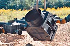
The SediPipe© system is composed of the following supplied pieces (cast iron cover, distribution crown, solids recovery basket, DOM seal and extension) :
- of an upstream chamber. The size of this chamber depends on the model.
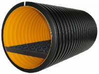
- of a 600 mm diameter sedimentation pipe incorporating an anti-remobilisation grid and a non-return valve, all installed with a counter slope.
- of a downstream chamber incorporating a siphon.
- optional :
- Absorption cartridge for the treatment of dissolved pollutants
- Upper grid in the sedimentation pipe for separation and storage of light liquids (SediPipe XL+©) model.
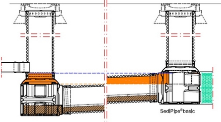
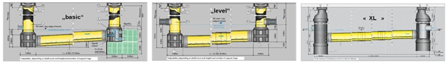
Illustration of different models
Depending on the different constraints of the project, different models can be considered. Each model offers a reliable, simple and long-lasting technical solution.
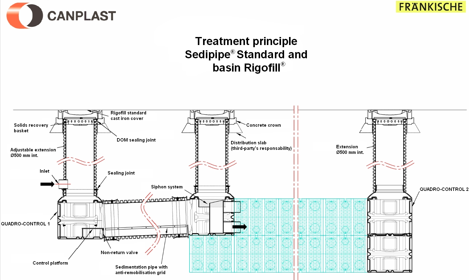
Sedipipe standard©
This model integrates directly with the Rigofill© module that allows infiltration or retention.
The installation of this upstream structure of a basin avoids the clogging of the basin.
In addition, the maintenance of the SediPipe© system is quick and easy. This model exists with a 6m or 12m long sedimentation pipe.
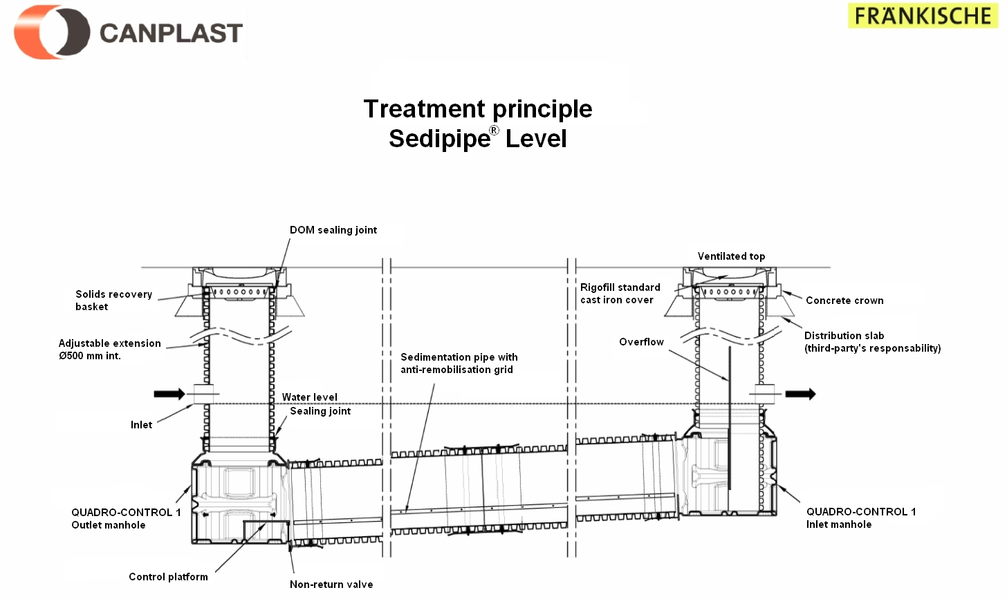
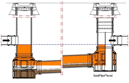
Sedipipe Level
This model fits directly into the plastic pipe network. The installation of this structure makes it possible to treat runoff water from a watershed. This model exists with a 6, 12, 18 or 24 m long sedimentation pipe.
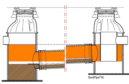
Sedipipe XL
This model fits directly into the plastic pipe network. The installation of this structure allows a greater volume of storage of pollutants. This model exists with a 6, 12, 18 or 24 m long sedimentation pipe.
Objectives and effectiveness of the SediPipe© system
- Protection of downstream structures and the receiving natural environment by treatment of Suspended Solids (SS) and associated pollutants.
- A system designed to avoid remobilisation of selected pollutants.
- In the event of an accident, the SediPipe© has a storage volume for hydrocarbons.
- Easy inspection and maintenance by flushing and suction.
- Compatible with Rigofill© modules which allow managing the quantitative problem of stormwater.
Design and effectiveness
The design principle of the SediPipe© is based on the approach of the first European recommendation, the DWA 153F "Recommendation regarding storm water treatment", which was published in August 2007 in Germany. The SediPipe© system has been the subject of several external studies, including the latest: "SediPipe: Research and Guidelines for Implementation", a study by TAUW/TU Delft (Delft University of Technology).
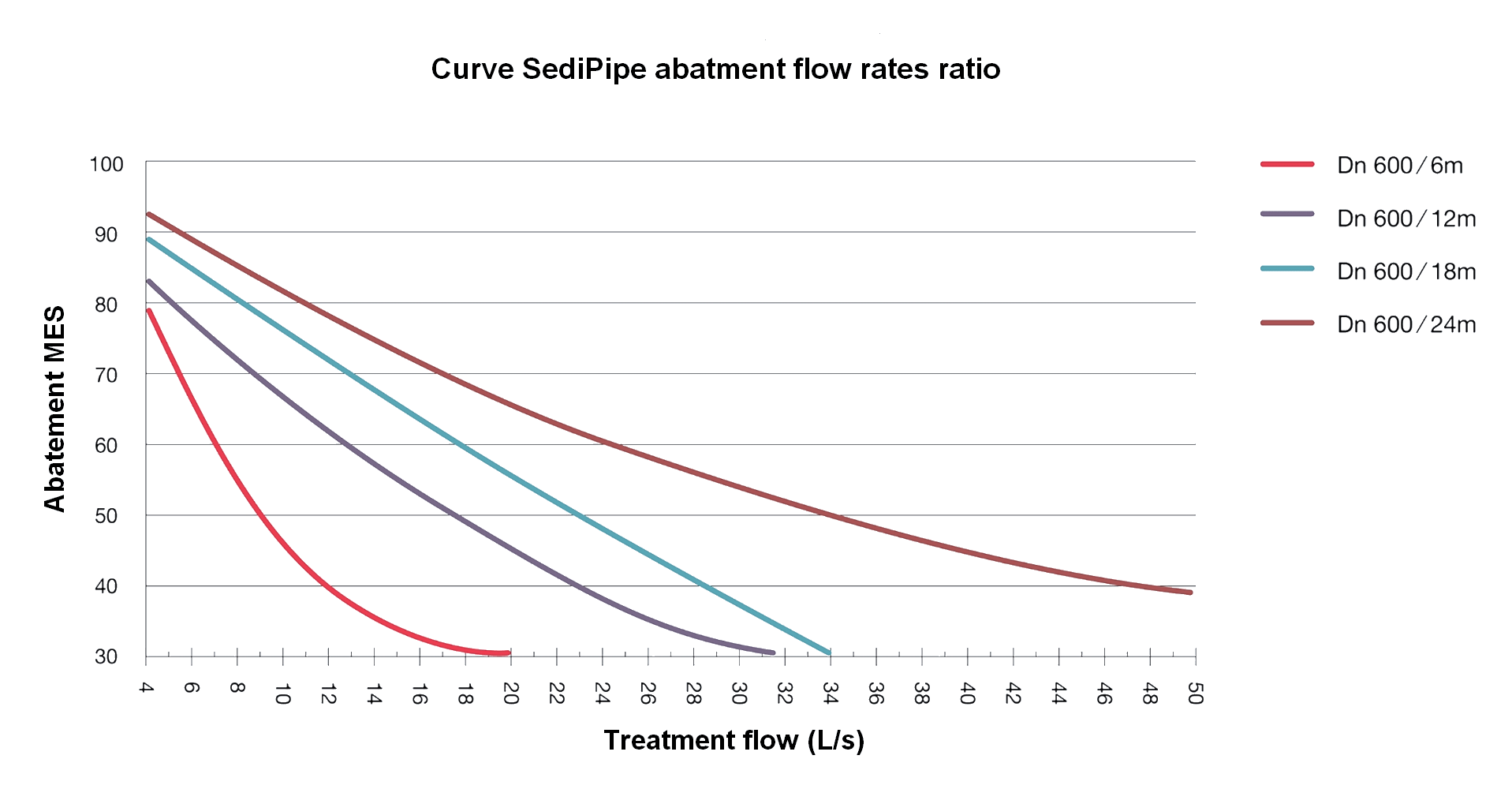
The SediPipe© system decants transported pollutants for rainfall periods of less than one year. The usual values for defining the intensity of rain can range from 10 l.s/Ha to 50 l.s/Ha.
Therefore, depending on the recommended abatement and the flow of the watershed, it is possible to easily design a SediPipe© system.
Transport and storage on site
On delivery, it is necessary to make sure that the elements are complete and undamaged. Do not assemble elements that are damaged. Unloading and transport to the excavation must be done with appropriate lifting equipment. Plastic elements must be protected from extreme heat. Pipes and manholes should be stored in the shade or covered with a clear tarpaulin impervious to light.
Earthwork
The general dimensions of the trench or excavation shall be in accordance with SIA 190. These dimensions must allow safe access to ensure the implementation.
Bedding
The bedding is to be made with materials suitable for compaction (e.g. sand/fine gravel). This will consist of a layer of 10 cm deep minimum on normal ground. This thickness depends on the quality and the load bearing capacity of the ground.
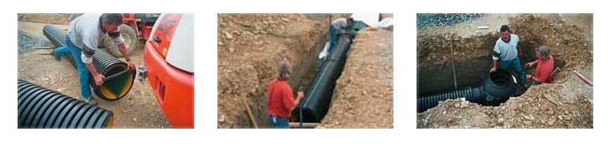
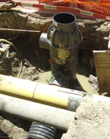
Installation of the system
1) Installation of the first manhole
The manhole (here inlet manhole) must be placed on the prepared bed at the right height and be prevented from slipping. You must be careful that the backfill material does not enter the manhole (using a protective cover).
2) Installing the sedimentation pipe
- The sealing joint must be placed in the first ring of the sedimentation pipe.
- Using lifting equipment, install the pipe in position. The marker at the top (white line) must be above. The effluent separator incorporated in the pipe must be below.
- Make sure that the seal is free of dirt and lubricated with the grease provided.
At the free end, use a lever arm to insert the sedimentation pipe into the chamber sleeve. The laying of the pipe is in a horizontal position. Then tilt the pipe so that it is slightly sloping. - When installing the double sleeve (only type 500/12 and 600/12), first mark the required 25 cm embedment depth on the pipe.
Only for type 500/12 and 600/12: deepen the bedding at the double sleeve.
When laying the pipes, make sure that the markings at the top of the pipe and the sleeve match.
3) Installation of the second manhole
The manhole (here outlet manhole) must be placed on the prepared bed at the right height. Then, you need to prepare the junction with a sleeve and push the manhole into the sedimentation pipe.
Figure 1: Procedure of the installation steps
Control
Before backfilling the system, check the following points :
1) Position and height difference of manholes according to plan specifications.
2) Horizontal position of the manholes.
3) Position and concordance of the marker at the top (white line at the top).
4) Axial position of the system
5) Control of the embedment depth at the manhole level
6) Only for type 500/12 and 600/12 Control of the embedment depth at the double sleeve.
7) Watertightness tests.
8) Put the protective cover back on the manholes !
Backfill
The quality of the backfilling is important for the long-term durability of the structure.
SIA 190 defines the general laying principle. The apron, the lateral filling and the covering must be made with a compactable material free of crushed stones. On the sides of the pipe, compact the material so that the bottom of the pipe rests entirely on the compacted ground. Cover the pipe with at least 30 cm of backfill.
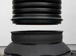
Installation of the extensions
The sealing joint must be inserted on the first ring of the extension and must be lubricated. The protective covers must be removed in order to insert the extension at the cone of the manhole. Make sure the ends are free of dirt.
The length of the extension needs to be levelled to the base plate. The DOM sealing joint must be positioned in the last ring. The recovery basket of the solids can subsequently be disposed thereafter at the top of the extension. The concrete crown and cover are installed in a traditional way.
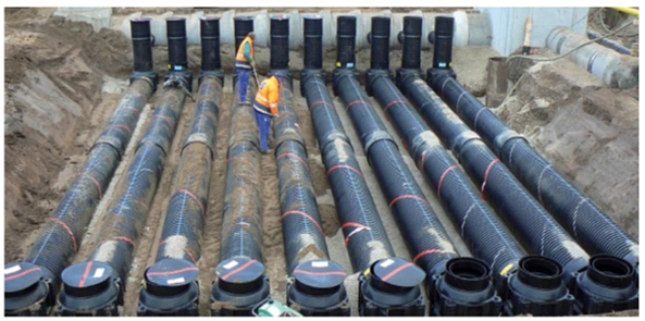
Some achievements
SediPipe© Level 12, 18 and 24 m
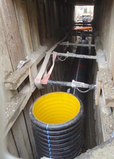
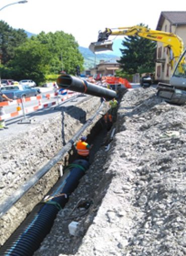
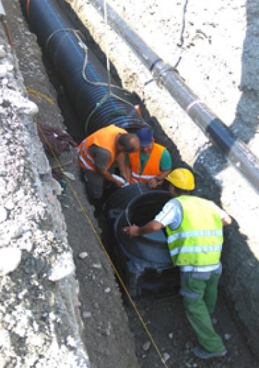
SediPipe XL© 24 m
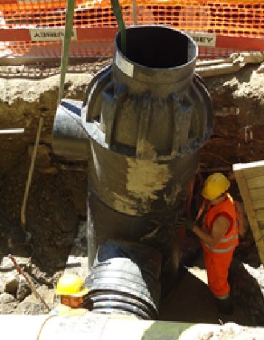
Description of the installation
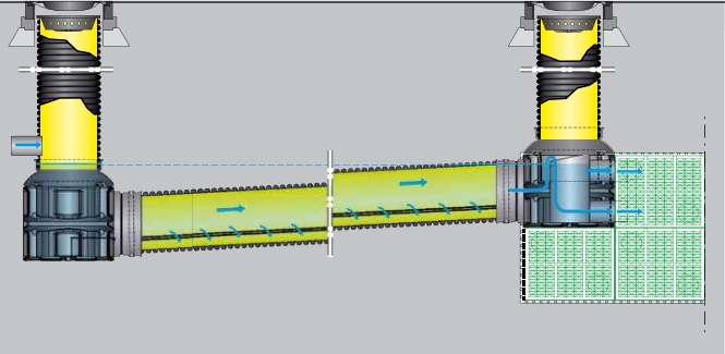
SediPipe© rainwater treatment systems are used to treat stormwater pollution in traffic areas. In operation, the installation is filled with water; it works with a continuous water flow.
The system separates solids and pollutants from the stormwater and stores the captured sludge in the treatment system. The sludge chamber should be cleaned regularly.
In addition, the installation has a device allowing it to capture some of the light liquids such as petrol or used oil. This function is exclusively used as a precautionary measure in the event of an accident, since this structure is not a hydrocarbon separator in the sense of the EN 858 standard.
The capture of light liquids cannot be done in a turbulent environment. Facilities can capture the following quantities of light liquid :
| Product | Light liquids storage capacity (liters) |
Sludge storage capacity (liters) |
| SediPipe Basic© | ||
| 600/6 | 320 | 280 |
| 600/12 | 520 | 490 |
| SediPipe Level© | ||
| 600/6 | 1'160 | 280 |
| 600/12 | 1'920 | 490 |
| SediPipe XL© / XL+© | ||
| 600/6 | 2'000 | 680 |
| 600/12 | 3'160 | 890 |
| 600/18 | 4'340 | 1'100 |
| 600/24 | 5'520 | 1'300 |
| Sedisubstrator XL© | ||
| 600/12 | 3'800 | 890 |
| 600/18 | 5'370 | 1'100 |
| 600/24 | 6'930 | 1'300 |
| Light liquids | Sludge |
Figure 1: Illustration of the capture volumes of the different SediPipe© models
General information concerning maintenance
The maintenance work will be carried out by a company specialising in the maintenance of networks, using a cleaning device. During the initial maintenance and in special cases, a video camera inspection is recommended.
Extracted materials should be disposed of properly.
All maintenance of inlet and outlet manholes can be done from the surface. The manholes are not easy to visit but are accessible. All equipment will be systematically introduced from the inlet manhole.
- The inlet manhole is the lowest point of the system; it is from here that the full system will be pumped out.
- Then the high pressure cleaning nozzle and/or the inspection cameras will be introduced into the sedimentation section. The introduction of equipment is facilitated by a service hatch in the inlet manhole.
- The maintenance of the system is done under the same conditions as the conventional maintenance of plastic pipes. (Pressure 80-120 bar and the use of a rotating nozzle).
The volumes of sludge captured by SediPipe© systems depend on local conditions. Indeed, this can vary according to the region (rainfall) and the land use (volume of pollutants). The cleaning interval should be estimated based on the experience of the teams in place. When setting-up an installation, it may result a greater amount of captured material.
It is recommended to clean the system after installation in order to receive an immaculate system. It is also recommended to carry out the first cleaning after the first year of operation to determine the amount of dirt captured under the current operating conditions. Depending on the state of fouling observed before cleaning, larger intervals will be defined. The standard values are shown in the table below:
|
Type of structure
|
Captured surface (m2)
|
Maintenance intervals (years)
* on the basis of 800 kg/ha * a (dry matter) |
|
SediPipe Standard© DN 600/6mSediPipe Level© DN 600/6m |
1'750
|
3
|
|
2'500
|
2
|
|
|
4'000
|
1
|
|
|
SediPipe Standard© DN 600/12 mSediPipe Level© DN 600/12 m |
2'500
|
3
|
|
4'000
|
2
|
|
|
5'500
|
1
|
Table 2: Standard maintenance interval
In the case of an oil spill, the installation must be cleaned immediately. In the absence of cleaning, subsequent rain can lead to a release of small quantities of hydrocarbons.
- Preparation
Before beginning the intervention, take all the necessary measures (signage of the work site and safety in relation to the traffic). Respect the applicable standards. Remove the manhole covers.
- Initial maintenance
It is recommended that the first maintenance of a SediPipe© installation be done after one year of operation. So the actual sludge production can be examined by camera inspection. In order to make an estimation of the volume of the sludge, it is imperative to gently draw water from the system. So that he sediment remains in the settling system and can be examined to determine the quantity. The system must then be cleaned using a high pressure washer. Nozzle cleaning can also be the subject of a camera inspection. When sediment accumulation is known, the maintenance interval must be established to consider regular maintenance. The estimated maintenance interval can be defined in Table 2 above.
- Control service
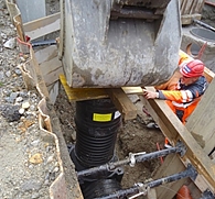
- Drainage : During regular maintenance, the system is cleaned by fast and powerful suction of water and sediment. Most of the sediment is found in the settling zone of the pipe. After this task is completed, the sedimentation zone is accessed via the inlet manhole.
- Cleaning : After draining the system, proceed to the cleaning of the structure; a rotating nozzle is recommended. It must be inserted into the sedimentation pipe. The drain pipe should be held at the bottom of the inlet manhole, at the base of the sedimentation pipe, as shown in figures below. This operation must be repeated once or twice.
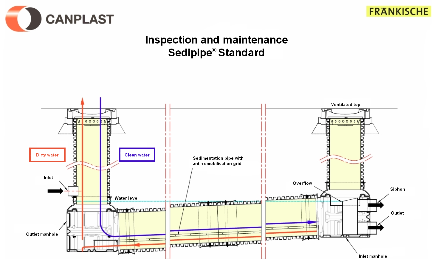
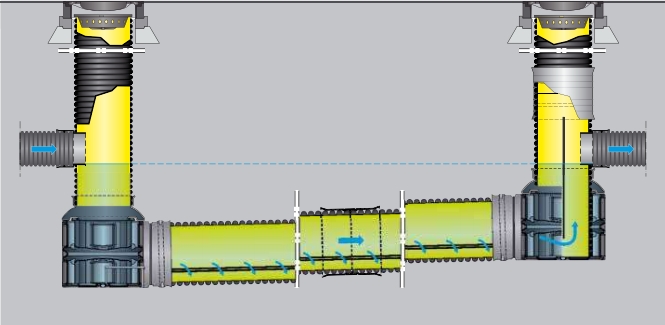
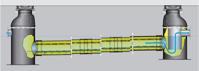
Figure 2: Inspection and maintenance SediPipe Standard©
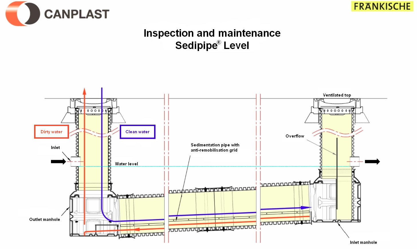
Figure 3: Inspection and maintenance SediPipe Level©
Applications
Decanted stormwater treatment system for the abatement of suspended solids (SS) and associated pollutants in urban areas.
Characteristics
- PE upstream manhole with inspection plate
- PP pipe, SN8, Ø 630 mm with non-return valve and anti-remobilisation grid
- PE downstream manhole with siphon
- Directional inputs and outputs
- Insertion of a filter cartridge is possible; absorption treatment
- Access by cast iron cover on distribution slab
Range
- Complete range: 6 , 12, 18 and 24 m
- Different heights available and adjustable according to the project for a water line of up to 4m high
- Optional coalescence grid
- Different models available
Qualities and advantages
- Lightness, ease and speed of installation
- Loss of level between upstream and downstream non-existent
- Adaptability according to the desired treatment
- Guaranteed watertight
- Mechanical resistance to impact, abrasion and corrosion
- Ease of operation and maintenance, brightness (yellow interior)
- Dimensional compatibility with all smooth plastic pipes
- Longevity of PE/ PP networks
- Recyclable elements