


Downstream Defender® is an effective solution for advanced hydrodynamic vortex separation of sediments, floating solids and light liquids present in runoff waters. By ensuring the non-release of the pollutants, which are collected and stored, the system protects the receiving environment from harmful pollutants.
Application
Rainwater treatment before storage, retention, discharge and infiltration.
Operation
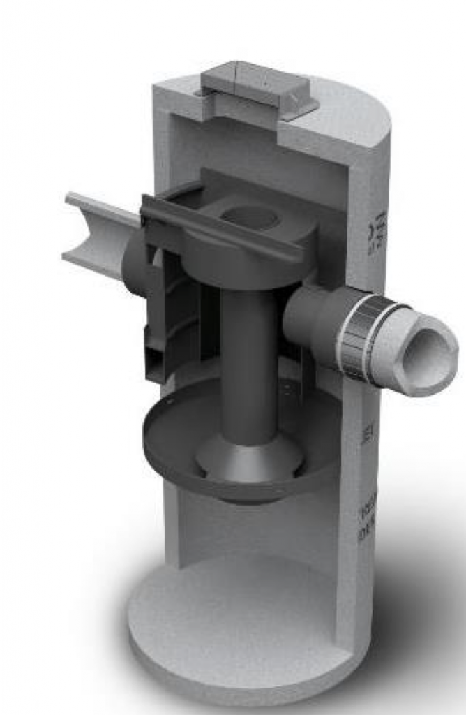
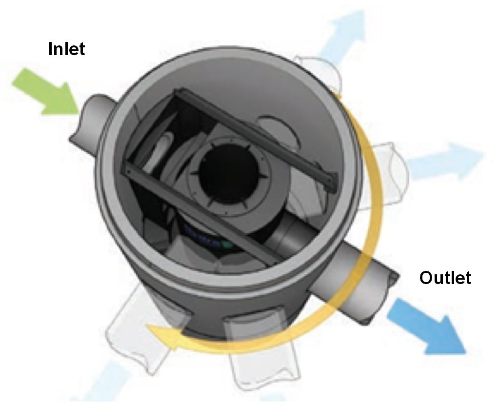
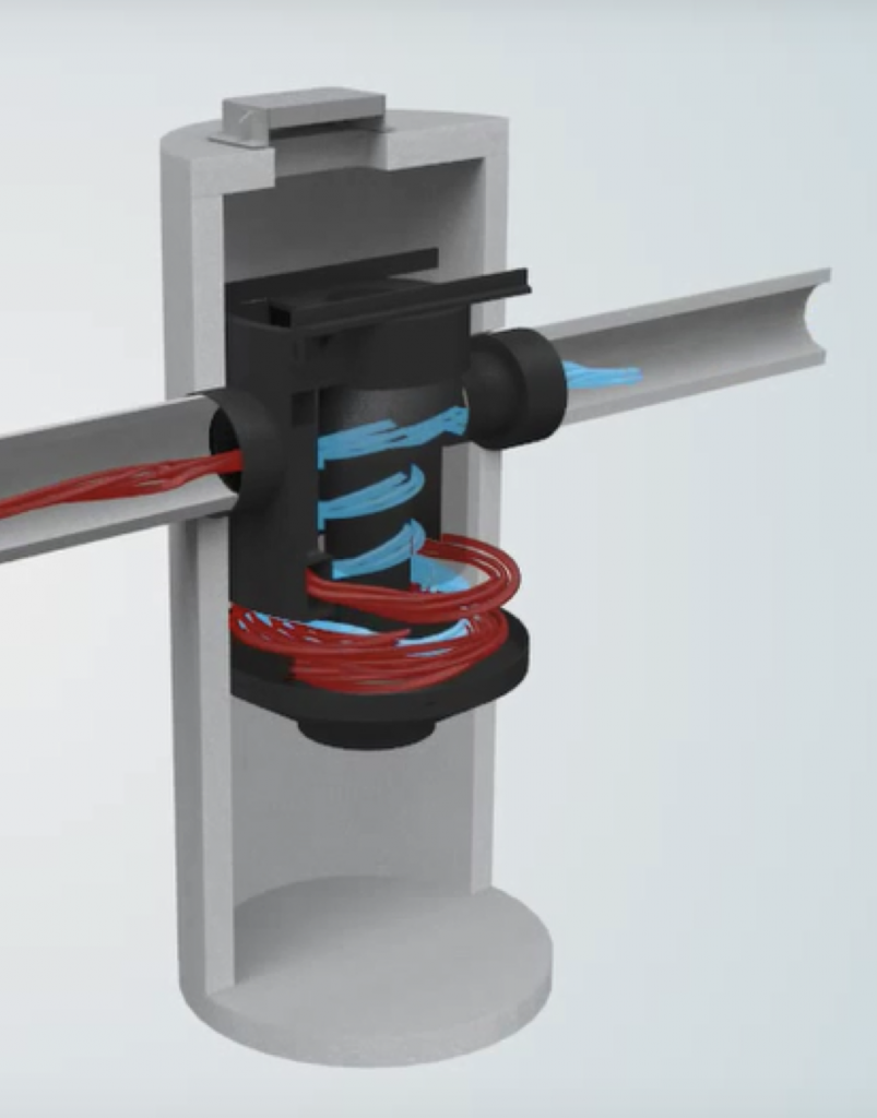
The internal components of the Downstream Defender® have been carefully designed to create a low-intensity rotational flow in the system in order to optimise the separation of pollutants. This vortex separation allows the sediments to be stored in the lower part of the containment zone while oils, floating solids and other light elements are stored in the upper part.
The bypass makes it possible to immediately direct exceptionally heavy rains toward the output. This design avoids turbulent flows and therefore prevents the release of captured pollutants. In addition, the low energy vortex separator generates a tranquilised flow, thus preventing the re-suspension of pollutants captured during heavy rainfall.
Efficiency
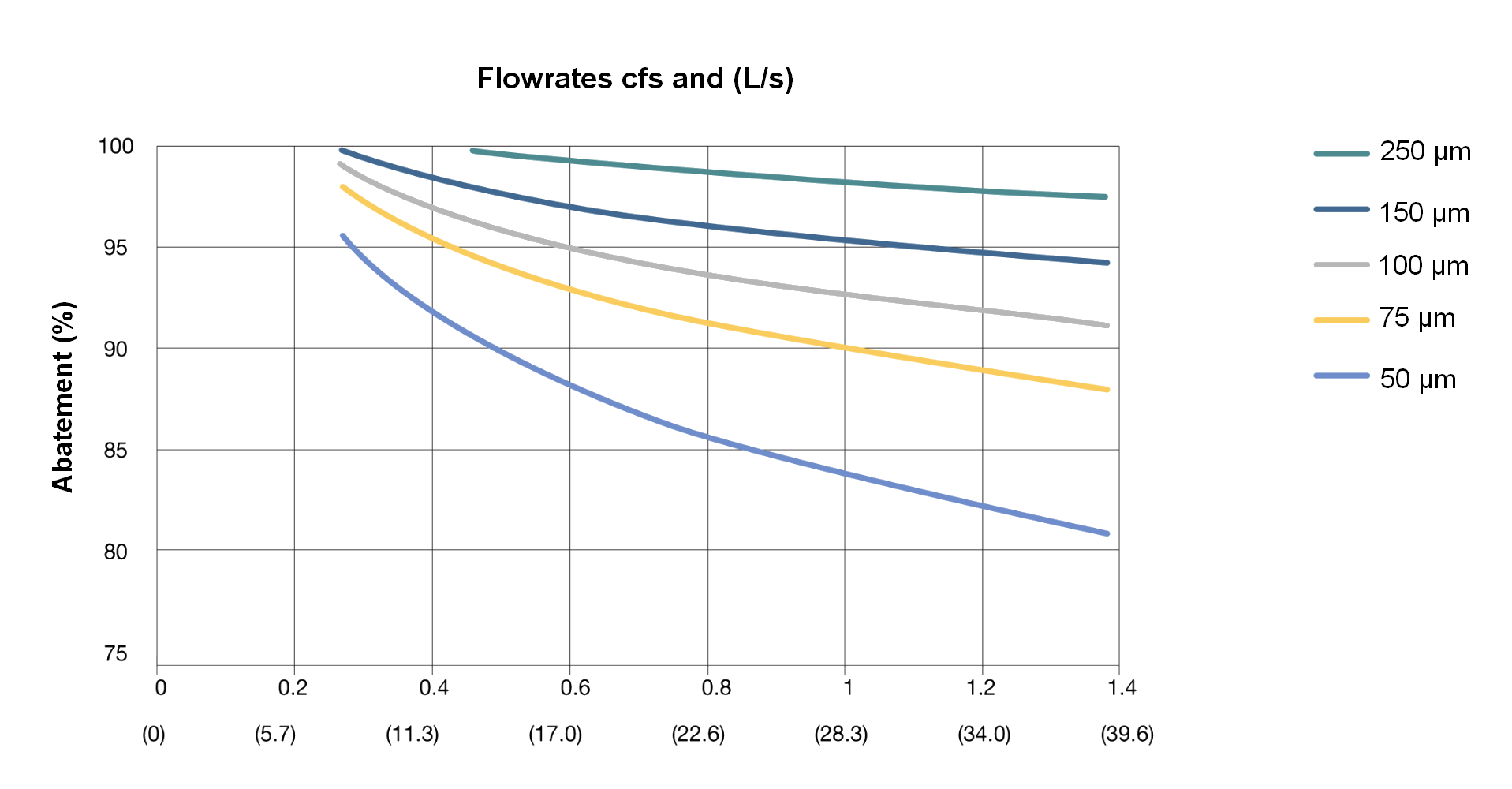
Three models/dimensions are currently available and their efficiencies are shown in the following table, for a TSS removal higher than 80%.
| Flow in l/s according to particle size | |||||
| Models | 50 µm | 75 µm | 100 µm | 150 µm | 250 µm |
| 1.2 | 39.1 | 62.4 | 80.7 | 85 | 85 |
| 1.8 | 88 | 140.3 | 181.6 | 226.5 | 226.5 |
| 2.55 | 156.2 | 249.6 | 322.9 | 424.8 | 424.8 |
Table 1: Effectiveness of the SS abatement according to particle size and flow per unit
- Example: Installing a 1.8m DN/ID int Downstream Defender® processing unit allows 80% of the MESs, of 50 microns or more, to be treated at a flow rate of 88 l/s.
The performance of the Downstream Defender® 1.2 model is illustrated in the following figure depending on particle sizes and flow rate.
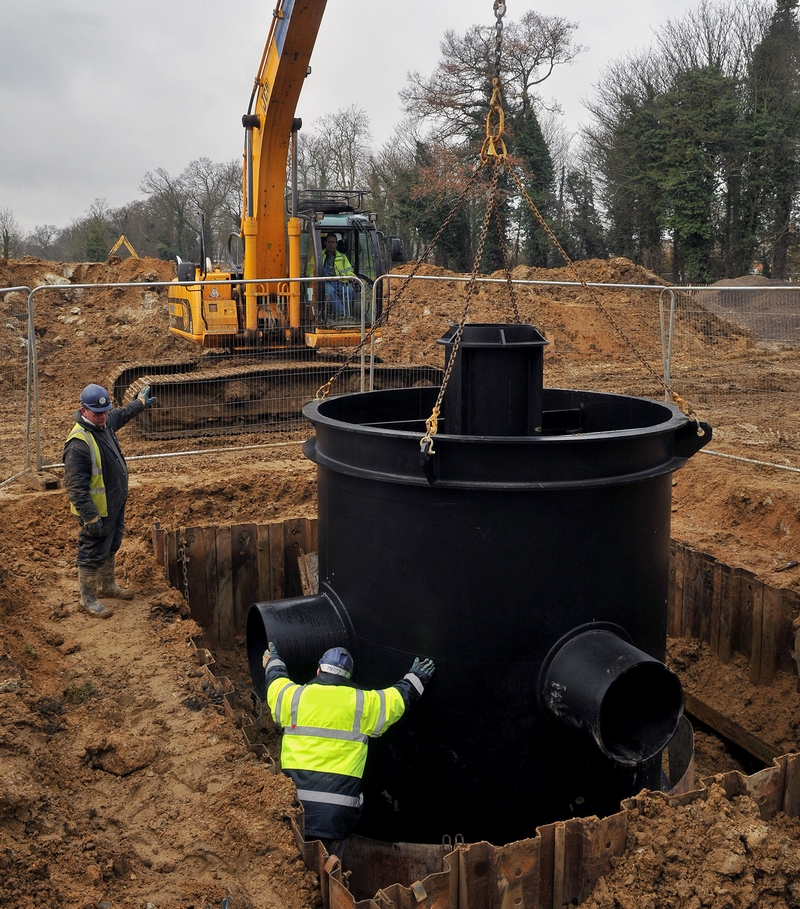
Implementation
Installing a Downstream Defender® system is as easy as installing a conventional plastic manhole. The system is delivered ready for installation. Please refer to the Downstream Defender® system technical data sheet.
Maintenance
The maintenance of a Downstream Defender® is simple and fast. The required operations are comparable to the maintenance of a dump chamber. A conventional vacuum truck, with no special equipment, is used to drain the system and return it to service after cleaning. No items need to be disassembled.
Adaptability
The Downstream Defender® system is made to measure according to the connection diameters of the network as well as their layout. The angles will be tailor-made according to the specificities of the project.
Physical principle
Illustration
Downstream Defender® protects the natural environment and storage structures by removing a wide range of pollutants from runoff.
General information
Downstream Defender® allows easy and safe inspection. A conventional cleaning truck is used to remove captured sediment and floating matter.
The point of access to the structure is in the upper part via the cover. The maintenance of removal of hydrocarbons, light liquids, floating and sludge is done from the outside. No human intervention within the system is necessary.
Maintenance operations do not require disassembly.
Maintenance schedule
The frequency of maintenance is determined on-site after installation. The frequency of maintenance is determined on the site after installation. During the first year of operation, the unit must be inspected every six months to determine the rate of sediment and floating matter accumulation.
This information can be recorded in the maintenance log (see end of document) to establish a routine maintenance schedule.
A visual inspection should be carried out once a year.
A system and network maintenance operation must be performed in the event of a spill.
The cleaning/suctioning procedure, of both sediment and floating solids and light liquids, typically takes less than 30 minutes.
Procedure
- Set up the necessary security equipment around the Downstream Defender® access as indicated by the applicable regulations,
- Remove the grill or cover from manhole,
- Without going into the manhole, look inside. Take note of any irregularities,
- Vacuum the floating solids and any light liquids at the top of the system (Figure 1),
- Then proceed with the suction of the sludge at the bottom of the manhole (Figure 2) through the central channel,
- Remove the suction hose,
- Return the system and the cover to clear water,
- Fill out the maintenance log.
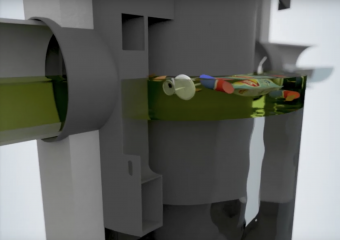
Figure 1 : Suction of floating solids and light liquids
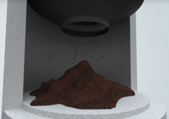
Figure 2 : Sludge suction